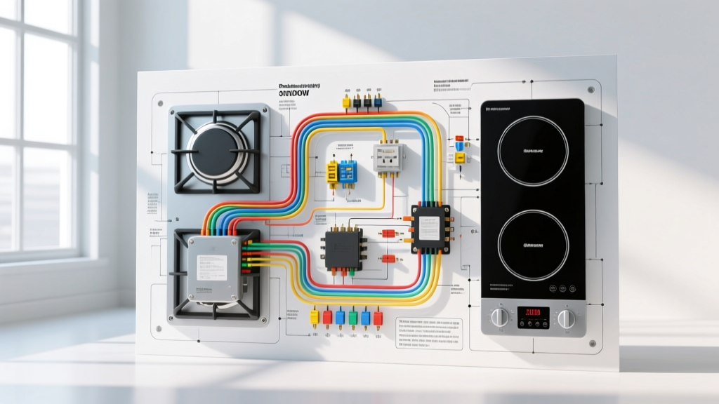
The Challenge of High-Draw Appliances in Camper Vans
Integrating high-wattage kitchen appliances into a vehicle's electrical system requires meticulous planning and strict adherence to automotive and RV electrical standards. When planning a camper conversion, finding a reliable wiring diagram for electric stove integration is critical, especially when transitioning from propane to all-electric induction cooktops. Unlike standard 12V DC accessories, a modern electric stove or induction cooktop typically draws between 1500W and 3000W of continuous AC power. This massive load demands a robust pure sine wave inverter, heavy-gauge DC cabling, and a seamless Automatic Transfer Switch (ATS) to alternate between off-grid battery power and shore power.
In this comprehensive walkthrough, we will detail the exact wiring schematic for installing a 2000W induction electric stove in a Ford Transit or Mercedes Sprinter camper conversion. This guide covers DC battery bank sizing, inverter selection, ATS logic, AC wire routing, and specific NEMA receptacle pinouts to ensure your mobile kitchen operates safely without triggering inverter faults or melting wire insulation.
System Architecture: Shore Power vs. Off-Grid Inverter
To run an electric stove in a motorhome or camper van, the electrical system must support a minimum 3000W continuous output inverter. The architecture relies on a dual-feed AC system managed by an Automatic Transfer Switch (ATS). When the vehicle is plugged into a 30-amp or 50-amp RV pedestal (shore power), the ATS bypasses the inverter and feeds the stove directly from the grid. When off-grid, the ATS switches to the inverter's AC output in under 50 milliseconds, preventing the stove's digital control board from resetting.
According to NEC Article 551 (Recreational Vehicles and Recreational Vehicle Parks), all high-draw AC appliances must be on dedicated branch circuits with appropriate overcurrent protection. Furthermore, the DC side of the system must comply with SAE J1113 standards for electromagnetic compatibility and voltage drop limits in vehicular environments.
Component Specification & Wire Sizing Chart
Before pulling any wire, verify that your components match the specifications below. Voltage drop is the enemy of high-wattage heating elements; a 3% drop on the DC side can cause the inverter to trigger a low-voltage cutoff when the stove ramps up to its maximum wattage.
| Component | Specification | Wire Gauge / Rating | Overcurrent Protection |
|---|---|---|---|
| Battery Bank | 12V LiFePO4 (Minimum 400Ah) | 2/0 AWG Welding Cable | 400A Class T Fuse |
| Inverter/Charger | 12V 3000W Pure Sine Wave | 2/0 AWG (DC), 10 AWG THHN (AC) | Integrated / 30A AC Breaker |
| ATS (Transfer Switch) | 30A 50ms Transfer Time | 10 AWG THHN Stranded | 30A Dual-Pole Breaker |
| Electric Stove Branch | 1800W - 2000W Induction | 10 AWG THHN (120V) | 20A Single-Pole Breaker |
| Stove Receptacle | NEMA 5-20R (120V 20A) | N/A | GFCI Protection Required |
Step-by-Step Wiring Diagram Walkthrough
Phase 1: DC Battery Bank to Inverter
The foundation of this wiring diagram for electric stove setups begins at the DC battery bank. A 2000W induction cooktop pulling 1800W continuously will draw approximately 150 Amps from a 12V system (accounting for 85% inverter efficiency).
- Main Fusing: Install a 400A Class T fuse on the main positive busbar within 18 inches of the battery positive terminal. This is non-negotiable for lithium battery safety.
- DC Cabling: Run 2/0 AWG pure copper welding cable from the positive busbar to the inverter's positive DC terminal. Use a hydraulic crimper to attach 3/8-inch ring terminals, and torque the inverter lugs to exactly 12 Nm (106 in-lbs) to prevent arcing under heavy load.
- Grounding: Connect the 2/0 AWG negative cable to the vehicle's dedicated auxiliary ground stud (e.g., Ford Transit BEM designated ground point M8) and the inverter's negative terminal. Do not ground the inverter directly to the battery negative; it must share the same ground potential as the chassis to prevent ground loop noise on the AC output.
Phase 2: AC Inverter Output to ATS
The AC output of the inverter must be routed to the 'INVERTER IN' port of the Automatic Transfer Switch (ATS).
- Use 10 AWG stranded THHN wire (Black for Hot, White for Neutral, Green for Ground).
- Install a 30A double-pole AC breaker between the inverter and the ATS to serve as a manual disconnect switch. This allows you to physically isolate the inverter's AC output during maintenance.
- Ensure the Green ground wire is bonded to the ATS grounding busbar, which ultimately ties back to the vehicle chassis ground.
Phase 3: Shore Power Integration & Stove Receptacle
The 'SHORE IN' port on the ATS receives power from the vehicle's exterior 30-amp marine inlet. The 'LOAD OUT' port on the ATS feeds the main AC sub-panel.
- Route the ATS load output to a dedicated AC sub-panel (e.g., Blue Sea Systems 120V AC Panel).
- Install a 20A single-pole breaker dedicated exclusively to the electric stove circuit.
- Run 10 AWG Romex or THHN in a flexible liquid-tight conduit from the breaker to the NEMA 5-20R receptacle mounted in the van's kitchen cabinetry.
- Because the stove is located near a kitchen sink, NEC codes dictate that this receptacle must be GFCI protected. Use a 20A GFCI receptacle or a GFCI breaker in the sub-panel.
NEMA Receptacle Pinouts for Electric Stoves
Understanding the correct pinout is vital when terminating the AC wiring at the stove's receptacle. Most portable 120V induction cooktops use a NEMA 5-15P or 5-20P plug. Hardwired RV drop-in electric stoves may require direct terminal block connections. Below is the standard pinout for the NEMA 5-20R receptacle used in this diagram:
| Terminal Designation | Wire Color | Function | Voltage / Amperage |
|---|---|---|---|
| Hot (Brass Screw) | Black | Line 1 (120V AC) | 120V / 20A Max |
| Neutral (Silver Screw) | White | Return Path | 0V Reference |
| Ground (Green Screw) | Green / Bare | Equipment Grounding | Safety Fault Path |
Note: If you are installing a 240V residential electric stove in a large 50-amp Class A motorhome, you will need a NEMA 14-50R receptacle, which requires two hot legs (Red and Black), a Neutral (White), and a Ground (Green), fed by a split-phase inverter or a 50-amp shore power pedestal.
Troubleshooting Common Inverter & Stove Faults
Even with a perfect wiring diagram for electric stove integration, real-world vehicular environments introduce variables that can cause system faults. Here is a diagnostic tree for common issues:
- Symptom: Inverter shuts down immediately when stove is turned to 'High'.
Cause: Voltage sag on the DC side triggering the inverter's Low Voltage Cutoff (LVC).
Fix: Measure DC voltage at the inverter terminals (not the battery) while the stove is running. If it drops below 10.5V, your 2/0 AWG cables are too long, or your battery BMS is limiting discharge current. Upgrade to 4/0 AWG or add a parallel battery. - Symptom: Stove displays 'E0' or 'U' error code and beeps.
Cause: Dirty power or incorrect frequency from the inverter.
Fix: Verify the inverter is outputting a Pure Sine Wave (PSW). Modified Sine Wave (MSW) inverters will destroy the induction cooktop's internal rectifier and trigger protection faults. Check AC frequency with a multimeter; it must be exactly 60Hz (±0.5Hz). - Symptom: GFCI breaker trips when switching from Shore Power to Inverter.
Cause: Neutral-to-Ground bonding conflict.
Fix: The inverter must have an internal relay that disconnects the neutral-ground bond when shore power is active, and reconnects it when off-grid. Ensure your ATS is wired exactly to the manufacturer's schematic to prevent duplicate neutral-ground bonds, which cause stray currents that trip GFCIs.
Safety Standards and Authoritative References
Designing vehicular electrical systems for high-draw appliances requires adherence to strict safety codes. Always consult the following resources before energizing your system:
- Victron Energy Wiring Unlimited Guide: Essential reading for inverter/charger grounding and neutral-bonding logic in mobile applications (Victron Energy PDF).
- NEC Article 551 (Recreational Vehicles): The definitive code for RV branch circuits, GFCI requirements, and ATS installation standards.
- Ford Motorhome Body Equipment Manual (BEM): Provides exact chassis ground stud locations and auxiliary alternator wiring diagrams for Transit-based camper builds.
By following this exact schematic and respecting the physical limits of copper wire and lithium BMS systems, your electric stove will provide reliable, off-grid cooking capabilities without compromising the safety of your vehicle's electrical network.