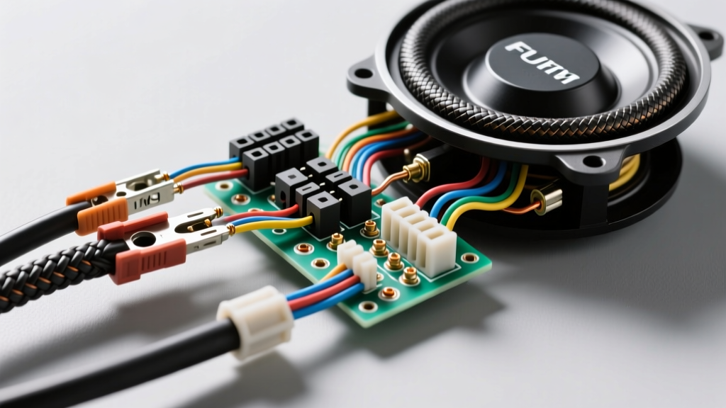
Decoding the Standard Car Sub Wiring Diagram
Installing a high-output subwoofer system requires more than just following a generic car sub wiring diagram; it demands a strict adherence to electrical physics, impedance matching, and material science. A properly executed mobile audio installation minimizes voltage drop, eliminates electromagnetic interference (EMI), and ensures your amplifier operates within its safe thermal and electrical limits. Whether you are wiring a single 12-inch subwoofer or a competitive SPL build with multiple 15-inch drivers, understanding the core architecture of your wiring schematic is critical.
Every comprehensive car sub wiring diagram is divided into four primary circuits: the high-current power delivery system (12V+ and Ground), the low-current control circuit (Remote Turn-On), the signal transmission path (RCA or High-Level), and the speaker output load. Misinterpreting any of these circuits—such as using undersized power wire or improper voice coil configurations—will result in catastrophic amplifier failure, alternator damage, or severe audio clipping.
Amp Kit Material Comparison: OFC vs. CCA
Before routing a single cable, you must select the correct amplifier wiring kit. The mobile audio industry is currently flooded with Copper-Clad Aluminum (CCA) wire disguised as pure copper. When analyzing a car sub wiring diagram, the power and ground specifications are calculated based on the conductivity of pure copper. Using CCA wire on a high-wattage system introduces dangerous levels of resistance and heat.
| Specification | Oxygen-Free Copper (OFC) | Copper-Clad Aluminum (CCA) |
|---|---|---|
| Conductivity Rating | 100% IACS Standard | ~65% to 70% IACS |
| Heat Dissipation | Excellent; runs cooler under heavy load | Poor; prone to thermal runaway at high amperage |
| Corrosion Resistance | Highly resistant to oxidation | Prone to galvanic corrosion under insulation |
| Flexibility & Fatigue | High strand count, resists vibration breakage | Brittle; strands snap under chassis vibration |
| Recommended Use | All systems, especially >500W RMS | Low-power systems (<200W RMS) only |
According to the Consumer Technology Association (CTA), mobile power wire must meet strict CTA-2015 standards. Always verify that your kit is certified CTA-2015 compliant OFC before beginning your installation.
Voice Coil Impedance Configurations
The most complex section of any car sub wiring diagram is the voice coil configuration. Amplifiers are designed to deliver maximum RMS power at specific impedance loads (typically 4-ohm, 2-ohm, or 1-ohm). Wiring your subwoofers to an impedance lower than your amplifier's stable rating will trigger thermal protection or blow the output transistors.
Dual Voice Coil (DVC) Wiring Matrix
The following matrix outlines the final impedance loads for the most common subwoofer configurations. Use this to match your amplifier's stable ohm load.
| Subwoofer Type | Series Wiring | Parallel Wiring | Series-Parallel (Multiple Subs) |
|---|---|---|---|
| Single DVC 4-Ohm | 8 Ohms | 2 Ohms | N/A |
| Single DVC 2-Ohm | 4 Ohms | 1 Ohm | N/A |
| Two DVC 4-Ohm Subs | 16 Ohms | 1 Ohm | 4 Ohms (Recommended) |
| Two DVC 2-Ohm Subs | 8 Ohms | 0.5 Ohms (Dangerous) | 2 Ohms (Recommended) |
Pro-Tip: When wiring in series-parallel, ensure all voice coils are identical. Mixing a 2-ohm coil with a 4-ohm coil in a series circuit will cause uneven power distribution, leading to mechanical failure of the subwoofer suspension.
CTA-2015 Compliant AWG Power Wire Sizing
Wire gauge selection is dictated by the total amperage draw of your amplifier(s) and the total length of the power and ground cable run. The SAE International J1113 standard outlines electromagnetic compatibility and voltage drop thresholds for automotive electrical systems. To prevent voltage drop below 12.5V at full output, consult the AWG sizing chart below.
| Amplifier Fuse Rating | 0-10 ft Run | 10-15 ft Run | 15-20 ft Run | 20+ ft Run |
|---|---|---|---|---|
| 0 - 20 Amps | 14 AWG | 12 AWG | 10 AWG | 8 AWG |
| 20 - 35 Amps | 12 AWG | 10 AWG | 8 AWG | 8 AWG |
| 35 - 50 Amps | 10 AWG | 8 AWG | 8 AWG | 6 AWG |
| 50 - 65 Amps | 8 AWG | 8 AWG | 6 AWG | 4 AWG |
| 65 - 85 Amps | 8 AWG | 6 AWG | 4 AWG | 4 AWG |
| 85 - 105 Amps | 6 AWG | 4 AWG | 4 AWG | 2 AWG |
| 105 - 125 Amps | 4 AWG | 4 AWG | 2 AWG | 1/0 AWG |
| 125 - 150 Amps | 4 AWG | 2 AWG | 1/0 AWG | 1/0 AWG |
| 150+ Amps | 2 AWG | 1/0 AWG | 1/0 AWG | 2/0 AWG |
Installation Note: The main power fuse (ANL or Class T style) must be installed within 18 inches of the vehicle's positive battery terminal. This protects the vehicle's harness in the event of a short circuit to the chassis.
OEM Integration: High-Level Signal Extraction
Modern vehicles utilize complex CAN-bus networks and factory amplifiers with built-in crossovers, signal smoothing, and volume-dependent EQ. Tapping into these signals requires a high-quality Active Line Output Converter (LOC). When reviewing your car sub wiring diagram for OEM integration, you must identify the correct twisted-pair speaker wires.
Signal Extraction Best Practices
- Twisted Pair Identification: OEM speaker wires are typically twisted together to reject Common Mode Noise. Always use a digital multimeter (DMM) to verify continuity and phase before splicing.
- Active LOC Selection: Use an LOC with load-matching capabilities (like the AudioControl LC2i or PAC LP7-2). Factory amps often check for a 4-ohm speaker load; failing to provide this load will trigger a 'Speaker Short' diagnostic trouble code (DTC) and mute the audio.
- Remote Turn-On Extraction: Do not tap into the vehicle's accessory fuse panel for the amplifier's remote turn-on lead (Blue/White wire). This can introduce alternator whine. Instead, use the LOC's built-in signal-sensing remote output, or tap into a low-amperage data-triggered circuit, such as the power antenna wire or a specific BCM (Body Control Module) output.
Troubleshooting Common Wiring Failure Modes
Even with a perfect car sub wiring diagram, real-world variables can introduce electrical faults. Below is a diagnostic decision tree for common mobile audio anomalies.
Symptom: Severe Alternator Whine (Engine RPM Pitch)
- Cause: Ground loop or improper RCA routing.
- Fix: Ensure the amplifier ground and the OEM head unit/LOC ground share the same chassis potential. Route RCA signal cables strictly down the opposite side of the vehicle from the high-current 12V power wire. If they must cross, do so at a strict 90-degree angle.
Symptom: Amplifier Thermal Shutdown During Heavy Bass Hits
- Cause: Severe voltage drop causing the amp's internal step-up power supply to overwork and overheat.
- Fix: Measure the voltage at the amplifier's power terminals using a DMM while playing a 40Hz sine wave at 75% volume. If voltage drops below 12.0V, upgrade your power wire by two AWG sizes, upgrade the Big 3 wiring (Alternator to Battery, Engine to Chassis, Battery to Chassis), or add a high-output alternator and lithium battery bank.
Symptom: Subwoofer Clipping / Distortion at Low Volume
- Cause: Factory head unit EQ or signal phase cancellation.
- Fix: Disable all factory bass boost and 'Speed-Sensitive Volume' settings. Verify subwoofer voice coil polarity using a 9V battery pop test or an audio phase tool. Out-of-phase dual subwoofers will cancel low frequencies and sound thin and distorted.
Final Torque and Termination Specifications
A wiring diagram is only as reliable as its physical connections. Never use 'scotch locks' or twist-ties for automotive audio. All power and ground connections must be terminated with closed-loop ring terminals, crimped with a hex-crimp tool, and sealed with marine-grade heat shrink. When securing the main ground wire to the vehicle chassis, remove all paint, primer, and rust down to bare steel using a wire brush or sanding disc. Secure the ground bolt (typically 8mm or 10mm) to manufacturer-recommended torque specifications (usually 15-20 ft-lbs) and coat the terminal in dielectric grease to prevent galvanic corrosion.