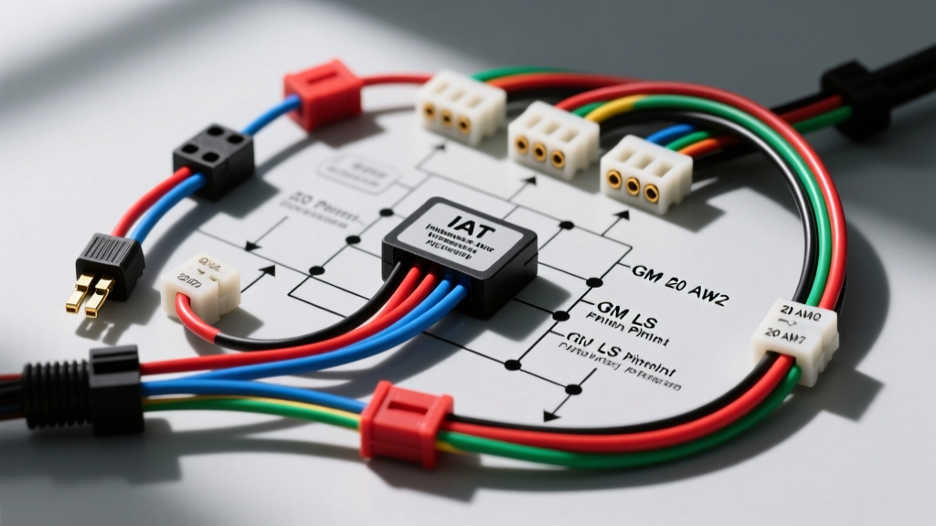
Understanding the IAT Sensor Wiring Diagram Topology
The Intake Air Temperature (IAT) sensor is a critical input for the Powertrain Control Module (PCM) to calculate air density, which directly influences fuel injector pulse width and ignition timing advance. When diagnosing drivability issues, lean/rich fuel trims, or specific diagnostic trouble codes (DTCs) like P0113 (IAT Circuit High) or P0112 (IAT Circuit Low), consulting an accurate IAT sensor wiring diagram is the mandatory first step. While modern vehicles often integrate the IAT thermistor into the Mass Air Flow (MAF) sensor housing, millions of vehicles—particularly the ubiquitous GM Gen III and Gen IV LS-based V8 platforms—utilize a standalone 2-wire IAT sensor mounted directly in the intake tube or manifold.
According to AA1Car Automotive Sensor Diagnostics, a standalone 2-wire IAT sensor operates as a Negative Temperature Coefficient (NTC) thermistor. The PCM supplies a 5-volt reference signal through an internal pull-up resistor (typically 5k to 10k ohms). As intake air temperature increases, the thermistor's internal resistance drops, allowing more voltage to bypass to the sensor ground circuit. The PCM monitors this voltage drop to calculate the exact air temperature. Understanding this voltage divider topology is crucial for interpreting the wiring schematic and executing the troubleshooting flow below.
Reference Table: GM Gen III/IV LS 2-Wire IAT Pinout
Before testing, verify your specific harness against this standard GM LS truck and passenger car 2-wire IAT configuration. Always cross-reference with your specific year's OEM service manual, as PCM connector cavity numbers can shift between the 1999-2006 and 2007+ generations.
| Sensor Pin | Wire Color | AWG | PCM Connector / Pin | Circuit Function |
|---|---|---|---|---|
| A (Signal) | Yellow (CKT 472) | 20 AWG | C1 (Blue) / Pin 25 | 5V Reference / IAT Signal Return |
| B (Ground) | Black/White (CKT 1472) | 20 AWG | C1 (Blue) / Pin 7 | Low Reference / Sensor Ground |
Step 1: Visual Inspection and Connector Integrity
Electrical faults in sensor circuits are rarely caused by a failed PCM; they are overwhelmingly rooted in physical harness degradation or connector failure. The GM LS IAT sensor utilizes a Delphi (Aptiv) Metri-Pack 150 series 2-way connector. These connectors are robust but susceptible to specific failure modes in high-heat engine bays.
- Inspect the Weather-Pack Seal: Check the silicone ribbed seal at the rear of the connector cavity. If it is missing, cracked, or swollen from oil intrusion, moisture will wick into the 20 AWG wire crimps via capillary action, causing internal copper oxidation and high resistance.
- Perform a Pin Drag Test: Disconnect the sensor. Using a spare, known-good male Metri-Pack 150 terminal, insert it into the female terminals on the harness side. You should feel a distinct mechanical 'click' and noticeable drag upon removal. If the test pin slides in without resistance, the terminal tension fingers are fatigued, leading to micro-arcing and intermittent IAT signal dropouts under vibration.
- Check for Heat Soak Damage: If the sensor is mounted in an aftermarket aluminum intake manifold near exhaust headers, inspect the wire insulation for brittleness. Standard cross-linked polyethylene (XLPE) insulation degrades rapidly above 125°C (257°F).
Step 2: KOEO Backprobing and Voltage Drop Analysis
If the visual inspection passes, proceed to live circuit testing. You will need a high-impedance Digital Multimeter (DMM) and fine T-pin backprobes. Never pierce the 20 AWG wire insulation with a probe, as this creates a moisture entry point that will eventually corrode the copper strands and alter the circuit resistance.
- Set your DMM to the 20V DC scale.
- Turn the ignition to Key On, Engine Off (KOEO).
- Backprobe the Yellow (Signal) wire at the rear of the sensor connector.
- Connect the DMM black lead to a known-good engine block ground.
Diagnostic Logic:
With a cold engine (ambient temperature roughly 68°F / 20°C), the thermistor resistance is high, meaning the PCM's 5V reference has nowhere to go. Your DMM should read between 4.7V and 4.9V. If you read 0V, the circuit is shorted to ground or the PCM 5V reference bus has collapsed. If you read exactly 5.0V or an open loop (OL), the circuit is open, or the sensor has failed internally with infinite resistance (triggering a P0113 code).
Start the engine and let it reach operating temperature. As the intake air warms, the voltage should smoothly sweep downward, typically settling between 1.5V and 2.2V at normal under-hood operating temperatures. Erratic voltage jumps indicate a failing thermistor element or a chafed wire intermittently shorting against the intake tube.
Step 3: Thermistor Resistance and Temperature Correlation
To isolate the sensor from the vehicle wiring harness, disconnect the IAT sensor and test the component directly. Set your DMM to the Ohms (Ω) scale. Measure the resistance across the two male pins on the sensor itself. Compare your findings to the standard GM NTC thermistor curve below:
| Temperature (°F / °C) | Expected Resistance (Ohms) | Tolerance Range (+/-) |
|---|---|---|
| 32°F (0°C) | 94,000 Ω | 5,000 Ω |
| 68°F (20°C) | 35,000 Ω | 2,000 Ω |
| 104°F (40°C) | 14,500 Ω | 1,000 Ω |
| 158°F (70°C) | 4,800 Ω | 400 Ω |
| 212°F (100°C) | 1,850 Ω | 150 Ω |
Troubleshooting Insight: If the resistance reads within spec at room temperature but drops to zero or spikes to OL when you apply heat from a heat gun, the thermistor's internal epoxy matrix has fractured. Replace the sensor. When installing a new threaded IAT sensor into an intake manifold, apply a minimal amount of thermally conductive sensor-safe thread sealant and torque to 15 lb-ft (20 Nm) to prevent manifold cracking or vacuum leaks.
Step 4: Harness Continuity and Short-to-Ground Testing
If the sensor tests perfectly but the PCM is still logging IAT codes or displaying skewed scanner data (e.g., showing -40°F when the engine is warm), the fault lies in the 20 AWG wiring harness between the sensor and the PCM.
- Disconnect the negative battery terminal to protect the PCM.
- Disconnect the PCM C1 (Blue) connector.
- Set your DMM to the lowest Ohms scale (usually 200Ω).
- Measure continuity from the harness-side sensor connector Pin A (Yellow) to PCM C1 Pin 25. The resistance must be less than 0.5 ohms. Anything higher indicates corroded copper strands or a failing splice in the harness.
- Repeat for Pin B (Black/White) to PCM C1 Pin 7.
Short Circuit Testing:
With both the sensor and PCM disconnected, place one DMM lead on the Yellow signal wire and the other on the engine block. The DMM should read OL (infinite resistance). If it reads any continuity, the Yellow wire is chafing against a metal bracket or the intake manifold, causing the 5V signal to short directly to ground, which the PCM interprets as an impossibly high air temperature (triggering P0112).
Step 5: EMI Interference and Wire Routing Verification
A frequently overlooked issue in modified or repaired vehicles is Electromagnetic Interference (EMI). The IAT sensor operates on a low-current, high-impedance analog voltage signal. According to SAE J1113 Electromagnetic Compatibility Standards, analog sensor circuits are highly vulnerable to inductive coupling from high-voltage ignition systems.
If you are diagnosing a vehicle that exhibits IAT signal dropouts specifically under heavy load or wide-open throttle (WOT), inspect the routing of the IAT harness. The 20 AWG Yellow signal wire must never be routed parallel to, or within 2 inches of, aftermarket ignition coil wires, spark plug leads, or high-current alternator charge cables. If the wiring diagram shows the harness crossing a high-voltage source, it must do so at a strict 90-degree angle to minimize the inductive field intersection. If EMI is suspected, wrapping the sensor pigtail in a tinned-copper braided shielding sleeve and grounding the shield to the PCM low-reference (not the engine block) will eliminate the induced voltage noise.
Summary of Diagnostic Outcomes
By following this structured flow based on the IAT sensor wiring diagram, you eliminate guesswork. A failed 5V reference points to a PCM or shared bus issue; an out-of-spec resistance points to the thermistor; and a continuity failure isolates the fault to the 20 AWG harness. Always verify mechanical connector integrity first, as a $0.50 spread terminal is statistically far more likely to cause an intermittent IAT code than a failed Powertrain Control Module.