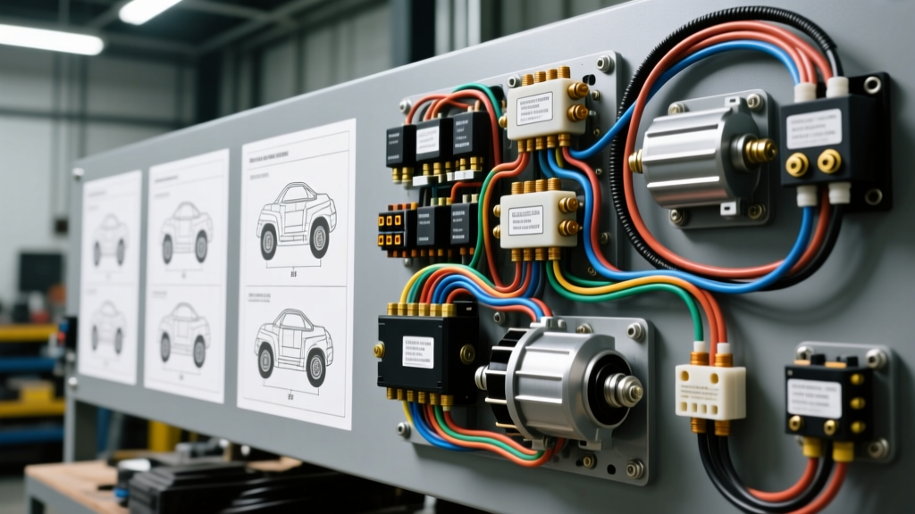
Understanding the Standard ATV Winch Wiring Diagram
When diagnosing powersport electrical failures, referencing an accurate wiring diagram for ATV winch systems is critical. Most modern 2500 lb to 4500 lb ATV/UTV winches utilize a 4-post DC contactor (often mistakenly called a solenoid) to reverse motor polarity. Unlike simple relay setups, this contactor handles massive inductive loads—often exceeding 150 amps under peak stall conditions.
The primary circuit relies on heavy-gauge stranded copper (typically 4 AWG or 6 AWG) to minimize voltage drop, while the secondary control circuit uses 14 AWG to 16 AWG wires routed through the handlebar rocker switch. Before testing, always disconnect the negative battery terminal to prevent accidental shorting of the un-fused high-amperage battery leads.
4-Post Contactor Pinout and Wiring Configuration
The industry-standard 4-post contactor (used by Warn, Champion, and Badland) routes power to the DC motor by alternating the ground and 12V+ feeds to the motor brushes. Below is the standard terminal configuration and wire color mapping.
| Terminal Post | Connection | Wire Color (Typical) | AWG Size | Connector Type |
|---|---|---|---|---|
| Post A (Top Left) | Battery Positive (+) | Red | 4 AWG / 6 AWG | 5/16" Ring Terminal |
| Post B (Top Right) | Motor Lead 1 | Yellow or Black/Stripe | 4 AWG / 6 AWG | 5/16" Ring Terminal |
| Post C (Bottom Left) | Motor Lead 2 | Yellow or Black/Stripe | 4 AWG / 6 AWG | 5/16" Ring Terminal |
| Post D (Bottom Right) | Chassis Ground (-) | Black | 4 AWG / 6 AWG | 5/16" Ring Terminal |
| Control Spade 1 | Ignition 12V+ Source | Red (16 AWG) | 16 AWG | 1/4" Spade / Quick Disconnect |
| Control Spade 2 | Switch Ground / Trigger | Black (16 AWG) | 16 AWG | 1/4" Spade / Quick Disconnect |
Step-by-Step Troubleshooting Flowchart
Use the following diagnostic decision tree to isolate faults within the winch electrical system. You will need a digital multimeter (DMM) capable of DC voltage and resistance testing, plus a heavy-duty load tester for voltage drop analysis.
Symptom 1: Winch Motor Does Not Run (No Contactor Click)
This indicates a failure in the low-amperage control circuit or a completely dead power feed to the contactor coil.
- Verify Battery Voltage: Connect the DMM across the battery terminals. Voltage must be above 12.4V. If below 12.0V, the contactor coil will not generate enough electromagnetic force to pull the heavy contacts closed.
- Test Control Power Feed: Reconnect the battery. Probe the Red 16 AWG wire at the contactor spade terminal with the ignition ON. You should read 12.0V - 12.6V. If 0V, trace the wire back to the ignition-switched fuse block or inline fuse holder (usually 15A or 20A ATC).
- Test the Rocker Switch Ground: Press the "IN" or "OUT" button on the handlebar switch. Probe the Black 16 AWG trigger wire at the contactor. It should show continuity to ground (near 0.0 ohms) when pressed. If open, the handlebar switch internal contacts are corroded—a common failure mode due to water ingress.
- Inspect Contactor Coil: If both control wires have correct signals but no click occurs, the internal contactor coil is burnt out. Replace the contactor assembly.
Symptom 2: Contactor Clicks but Motor Won't Turn
A distinct "click" confirms the control circuit is functioning and the coil is engaging. The fault lies in the high-amperage primary circuit or the motor itself.
- Perform Voltage Drop Test Across Contacts: Set DMM to DC Volts. Place probes on Post A (Battery +) and Post B (Motor 1). Press the winch button. A reading above 0.5V indicates pitted, carbon-scored, or welded internal contacts within the contactor. The contactor must be replaced.
- Check Motor Lead Continuity: Disconnect battery. Set DMM to Ohms. Measure resistance between Post B and the corresponding motor terminal. It should read less than 0.1 ohms. High resistance indicates a frayed 4 AWG cable or severe corrosion inside the crimped ring terminal.
- Test Motor Directly (Bench Test): Bypass the contactor entirely. Use heavy-gauge jumper cables to connect the battery positive directly to Motor Lead 1, and battery negative to Motor Lead 2. Caution: Expect heavy sparking. If the motor spins, the motor is good, and the contactor is definitively faulty. If the motor does not spin, the issue is internal to the motor (worn carbon brushes, seized armature, or shorted stator magnets).
Symptom 3: Winch Operates in One Direction Only
This is almost exclusively a control switch or secondary wiring issue, as the primary high-amp posts are shared for both directions.
- Isolate the Rocker Switch: The standard 5-wire or 6-wire handlebar rocker switch routes the ground signal to different contactor spades depending on the direction pressed. Unplug the switch harness at the main ATV wiring loom.
- Test Switch Continuity: Using the DMM in continuity mode, verify that pressing "Power Out" bridges the ground pin to the Yellow/Green trigger wire, and "Power In" bridges ground to the Brown/White trigger wire. Failure to bridge indicates melted internal switch contacts.
- Inspect Harness for Pinch Points: Trace the control harness from the handlebars down the steering stem. Look for zip-ties that are over-tightened, or areas where the harness rubs against the steering column, causing a 16 AWG wire to short to ground or break internally.
Technical Reference: Wire Gauge & Torque Specifications
Undersized wiring is the leading cause of premature contactor failure and winch motor burnout. Refer to this specification chart when replacing or extending winch wiring harnesses. Always use fine-stranded, pure copper wire conforming to SAE J1128 standards for low-tension primary cables.
| Winch Capacity | Min. Wire Gauge (AWG) | Max Length (One Way) | Terminal Torque Spec | Recommended Breaker |
|---|---|---|---|---|
| 1,500 - 2,500 lbs | 6 AWG Stranded | 6 Feet | 75 in-lbs (8.5 Nm) | 150 Amp Circuit Breaker |
| 3,000 - 4,500 lbs | 4 AWG Stranded | 8 Feet | 120 in-lbs (13.5 Nm) | 175 Amp Circuit Breaker |
| 5,000+ lbs (UTV) | 2 AWG Stranded | 10 Feet | 150 in-lbs (17 Nm) | 225 Amp Circuit Breaker |
Advanced Diagnostics: Testing the Automatic Mechanical Brake
While not strictly an electrical component, the automatic mechanical brake interacts directly with the motor's electromagnetic field. If your winch motor hums, draws excessive amperage (verified via an inductive DC clamp meter reading over 200A with no spool movement), but fails to pull, the mechanical brake may be seized.
To test this, disconnect the motor leads. Attempt to turn the motor armature shaft by hand using a pair of channel-lock pliers on the exposed shaft end (if accessible) or by carefully applying 12V directly to the motor terminals in short, half-second bursts. If the motor spins freely off-load but stalls immediately under a 50 lb strap tension, the brake cone is binding. This requires complete winch teardown, brake cone cleaning with isopropyl alcohol, and re-lubrication of the planetary gears with high-temp synthetic grease. Never apply dielectric grease inside the motor housing or brake assembly, as it will attract metallic dust from the carbon brushes and cause a dead short across the commutator.
Common Failure Modes and Environmental Factors
ATV and UTV winches operate in highly corrosive environments. Mud, water, and road salt accelerate galvanic corrosion, particularly at the dissimilar metal junctions between copper ring terminals and steel contactor posts. Always apply a liberal coating of dielectric grease or anti-oxidant paste (like Noalox) to all high-amperage connections before tightening to the specified torque.
Furthermore, the chassis ground (Post D) is a frequent point of failure. Never rely solely on the winch mounting plate for a ground path. A dedicated 4 AWG ground wire must be routed directly to the vehicle's negative battery terminal or a verified, unpainted chassis ground point bolted directly to the engine block. For more detailed OEM grounding topologies, consult the Warn Industries Installation Guides or your specific vehicle's factory service manual.
By systematically following this troubleshooting flow and adhering to strict AWG and torque specifications, you can reliably diagnose and repair ATV winch electrical faults, ensuring maximum pulling power and system longevity.