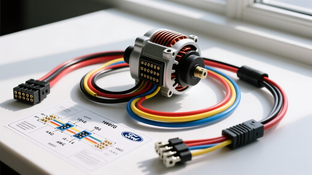
Understanding Your 1996 Mustang GT Alternator Wiring Diagram
If you are diving into the engine bay of a 1996 Ford Mustang GT, you are working with the legendary SN95 platform and the 4.6L 2V V8 engine. A critical component of this vehicle's electrical system is the charging system, specifically the Ford 3G series alternator. Whether you are diagnosing a dimming headlight issue, replacing a failed unit, or upgrading your audio system, understanding the 1996 Mustang GT alternator wiring diagram is your first step toward a reliable electrical system.
For beginners, automotive wiring schematics can look like a bowl of spaghetti. However, the Ford 3G alternator wiring is remarkably logical once you break it down into its core circuits. This guide will walk you through the OEM wire colors, AWG gauge requirements, pinout configurations, and real-world multimeter testing procedures to get your Mustang charging perfectly.
The Core Anatomy of the Ford 3G Charging System
The 1996 Mustang GT utilizes a 130-Amp large-case 3G alternator. Unlike older externally regulated Ford units, the 3G features an internal voltage regulator mounted directly to the rear of the alternator case. This design reduces wiring complexity and minimizes voltage drop, but it means the regulator plug and the main output cable are the primary failure points after decades of heat cycling and vibration.
According to the Haynes SN95 Mustang Repair Manual, the charging system is divided into two main harnesses: the heavy-gauge B+ output circuit and the low-tension 3-pin regulator control circuit. Let us break down both.
1. The B+ Output Circuit (Main Power)
The B+ terminal is the heavy stud on the back of the alternator where the main charging cable connects. This circuit carries the bulk of the amperage generated by the alternator back to the battery and the vehicle's main fuse block.
- Wire Color: Black with Orange Stripe (BK/OG) or Solid Black
- Wire Gauge: 4 AWG to 6 AWG (Stranded Copper)
- Routing: From the alternator B+ stud, down to the starter solenoid relay on the passenger side inner fender.
- Protection: Protected by a 175-Amp Mega Fuse located at the starter solenoid junction.
Expert Tip: When replacing this cable, always adhere to SAE J1128 standards for low-tension primary cables, ensuring you use high-strand-count copper wire to handle the thermal load and vibration of the 4.6L V8.
2. The 3-Pin Regulator Connector (Control & Sense)
The oval-shaped 3-pin connector plugs directly into the voltage regulator. This is where most beginners make wiring mistakes. The connector uses specific OEM wire colors to communicate with the ignition switch, the battery, and the dash cluster.
| Pin | Label | Function | OEM Wire Color | AWG Size |
|---|---|---|---|---|
| 1 | A (Sense) | Battery Voltage Sense | Orange / Light Blue (OG/LB) | 16 AWG |
| 2 | S (Stator) | Dash Charge Indicator / PCM | White (WH) | 18 AWG |
| 3 | I (Ignition) | Regulator Turn-On Signal | Yellow / Light Green (YE/LG) | 16 AWG |
Deep Dive: How the 3-Pin Circuits Actually Work
To troubleshoot effectively, you need to know what each wire is doing behind the scenes.
The 'A' Circuit (Battery Sense)
The Orange/Light Blue wire is the most critical wire for charging accuracy. It routes directly from the regulator plug to the positive terminal of the battery (or the starter solenoid battery post). The regulator uses this wire to 'read' the actual voltage at the battery. If your headlights are drawing heavy current and causing voltage drop across the main harness, the 'A' circuit tells the regulator to bump up the alternator's output to compensate. If this 16 AWG sense wire breaks or corrodes, the alternator will default to a base voltage, often resulting in an undercharged battery.
The 'S' Circuit (Stator / Dash Lamp)
The White wire connects to the instrument cluster charge indicator lamp and the OBD-II PCM. When you turn the key to the 'ON' position before starting the engine, the regulator grounds this circuit, illuminating the battery icon on your dash. Once the engine starts and the alternator begins generating AC stator voltage, the regulator removes the ground, and the dash light turns off. If this wire is shorted to ground, your battery light will stay on permanently, and the PCM may log a charging system diagnostic trouble code (DTC).
The 'I' Circuit (Ignition)
The Yellow/Light Green wire receives 12V from the ignition switch when the key is in the 'RUN' position. This 'wakes up' the internal voltage regulator. Without 12V on this pin, the alternator will not charge, even if it is spinning at 3000 RPM.
Beginner Multimeter Testing Guide
Before you buy a replacement alternator from your local auto parts store, grab a digital multimeter (DMM) and perform these fundamental tests based on Ford Motorcraft Service Documentation protocols.
Step 1: The Key-On Engine-Off (KOEO) Test
- Turn the ignition key to the 'ON' position (do not crank the engine).
- Verify the battery light on the dash illuminates. If it does not, check the 'S' circuit (White wire) and the dash bulb.
- Back-probe the 'I' pin (YE/LG) at the regulator plug. You should read full battery voltage (approx. 12.2V - 12.6V). If you read 0V, you have a blown ignition fuse or a broken wire between the ignition switch and the alternator.
Step 2: The Sense Wire Voltage Drop Test
- Keep the engine off.
- Set your DMM to DC Volts.
- Place the red probe on the positive battery post and the black probe on the 'A' pin (OG/LB) at the alternator plug.
- You should read less than 0.1V. If you read 0.5V or higher, the sense wire is corroded or damaged, and the regulator is receiving false voltage data.
Step 3: The Running Output Test
- Start the 4.6L V8 and let it idle.
- Measure voltage directly at the battery posts. You should see between 13.8V and 14.4V.
- Turn on the headlights, blower motor, and rear defroster to simulate a heavy electrical load.
- The voltage should remain above 13.5V. If it drops to 12.5V or lower, your alternator is failing to compensate, likely due to worn internal carbon brushes or a faulty regulator.
The Forgotten Element: Alternator Grounding
A wiring diagram is only half the story; the ground path completes the circuit. The 1996 Mustang GT alternator grounds through its aluminum mounting brackets to the cast iron engine block. From the engine block, the current must travel back to the negative battery terminal via the main engine-to-chassis ground straps.
Common Failure Mode: If the braided ground strap on the passenger side cylinder head is corroded or missing, the alternator will attempt to ground through the throttle cable or heater hoses, leading to melted cables and erratic charging. Always use a wire brush to clean the alternator mounting ears and the engine block mating surfaces before installation. Apply a thin layer of dielectric grease to prevent future galvanic corrosion between the aluminum alternator and iron block.
Essential Torque Specifications for the 4.6L 2V
When reinstalling your alternator or replacing the wiring pigtail, proper torque is vital to prevent snapped bolts or arcing terminals.
- Alternator Mounting Bolts (M10 x 1.5): 35 - 40 lb-ft (47 - 54 Nm)
- B+ Output Nut (M8): 106 lb-in / 9 - 12 lb-ft (10 - 12 Nm). Do not overtighten, or you will strip the threads on the rectifier plate.
- Regulator Plug: Push until the plastic locking tab audibly clicks. Apply a dab of silicone dielectric grease to the weatherpack seals to keep moisture out of the regulator pins.
Summary: Keeping Your SN95 Charging Strong
Troubleshooting the 1996 Mustang GT alternator wiring diagram does not require an engineering degree. By understanding the distinct roles of the B+ output cable, the A-sense circuit, the S-stator lamp circuit, and the I-ignition trigger, you can diagnose 99% of charging system faults with a basic multimeter. Always prioritize high-quality copper wiring, secure ground paths, and proper torque specs to ensure your 4.6L V8 keeps the lights bright and the battery fully charged for the next hundred thousand miles.