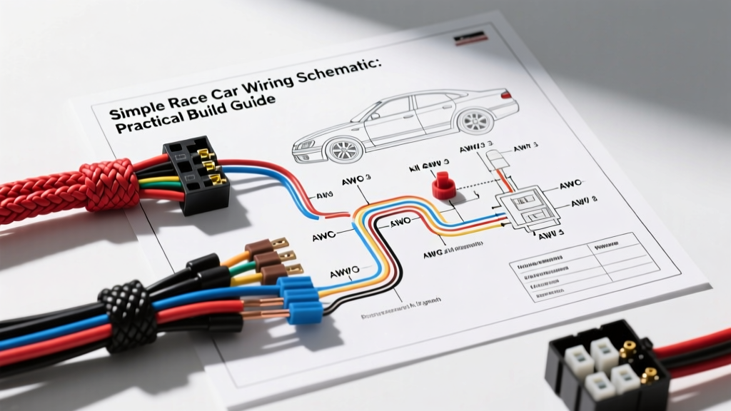
Why Ditch the OEM Harness?
Building a dedicated track car requires shedding unnecessary weight and eliminating complex failure points. A factory OEM harness can weigh over 40 lbs and contains miles of wire for ABS, HVAC, power windows, and infotainment systems. By designing and installing a simple race car wiring schematic, you reduce chassis weight, eliminate parasitic draw, and make trackside troubleshooting possible with a basic digital multimeter. This practical how-to guide walks you through building a reliable, lightweight, and sanctioning-body-compliant electrical system from scratch.
Core Components of a Race Car Electrical System
A dedicated race car schematic strips the electrical architecture down to its absolute essentials: cranking, ignition, fuel delivery, and safety cut-offs. There are no comfort circuits. Every wire must have a distinct purpose.
The FIA-Compliant Master Kill Switch
Sanctioning bodies require a master electrical disconnect that is accessible from outside the vehicle. According to FIA Appendix J Article 253.1.3, the master switch must cut all electrical circuits (except fire suppression) and stop the engine. To prevent the alternator from feeding back and keeping the engine running after the battery is cut, you must use a 6-terminal kill switch. This routes the alternator's field wire through a resistor/diode network, safely collapsing the magnetic field when the main battery power is severed.
Main Power Distribution Bus
Instead of daisy-chaining power from the ignition switch, route the main positive feed from the kill switch to a centralized, marine-grade power distribution bus. From this bus, individual relays and fuses branch out to the ECU, fuel pump, ignition coils, and cooling fans. This star-topography approach isolates faults and makes voltage-drop testing significantly easier.
Wire Selection: SAE Standards and AWG Sizing
Never use standard PVC-jacketed wire in a race car. Engine bay temperatures and vibration will degrade PVC insulation, leading to short circuits. You must use Cross-Linked Polyethylene (TXL, GXL, or SXL) wire, which meets SAE J1128 standards for high-temperature automotive applications. For extreme heat zones (e.g., routing near turbo manifolds or headers), upgrade to PTFE/Tefzel wire (MIL-W-22759/16).
| AWG Size | Max Ampacity | Insulation Type | Race Car Application |
|---|---|---|---|
| 1/0 AWG | 150A+ | Welding Cable | Battery to Starter Solenoid, Main Ground Strap |
| 8 AWG | 40A | TXL / GXL | Alternator Output, Main Kill Switch Feed |
| 10 AWG | 30A | TXL / GXL | Fuel Pump Power, Main Bus Feed |
| 12 AWG | 20A | TXL / GXL | Cooling Fans, Ignition Coils, Water Pump |
| 14 AWG | 15A | TXL / GXL | Relay Power Feeds, ECU Main Power |
| 18 AWG | 5A | TXL / Tefzel | Relay Triggers, Sensor Signals, Switch Logic |
Step-by-Step Installation Guide
Step 1: Battery and Kill Switch Routing
- Mount the battery securely in a lined aluminum or composite battery box. If relocated to the trunk, run 1/0 AWG positive cable through the cabin in a sealed conduit.
- Mount the 6-pole master kill switch on the rear bulkhead or firewall.
- Connect the 1/0 AWG positive cable from the battery to the 'IN' terminal of the kill switch.
- Run 8 AWG wire from the 'OUT' terminal of the kill switch to the main power distribution bus in the engine bay.
- Wire the alternator field wire to the auxiliary poles on the kill switch, incorporating a 10-ohm 10W ceramic resistor to bleed off residual voltage when the switch is thrown.
Step 2: Starter Solenoid and Ignition Trigger
Do not rely on the factory starter solenoid, as heat soak from race headers frequently causes no-crank conditions. Install a remote, continuous-duty solenoid (such as a Trombetta or Cole Hersee) mounted high on the firewall.
- Run 1/0 AWG cable from the kill switch output to the remote solenoid's main power terminal.
- Run 1/0 AWG from the solenoid's output terminal directly to the starter motor.
- Use 14 AWG wire to feed the solenoid's trigger terminal from a momentary 'Start' push-button switch on the dash.
- Wire an ignition toggle switch in series before the start button to prevent accidental starter engagement while the engine is running.
Step 3: Fuel Pump and ECU Power Relays
High-pressure EFI fuel pumps draw significant current (15A-25A). Never run fuel pump power directly through a dash switch.
- Mount a bank of 30A Bosch-style or Weatherpack relays near the ECU.
- Run 10 AWG power from the main bus to the relay's Pin 30 (Power In).
- Run 10 AWG from the relay's Pin 87 (Power Out) to the fuel pump, protected by a 25A inline MAXI fuse.
- Use 18 AWG wire to connect Pin 85 (Ground) to a clean chassis ground, and Pin 86 (Trigger) to an inertia/fuel cut-off switch on the dash, then to a 12V switched ignition source.
Grounding Strategy: The Star Point Method
The most common cause of erratic ECU behavior and sensor noise in race cars is poor grounding. Never 'daisy-chain' grounds from one component to the next. Instead, use a Star Point Grounding strategy. Weld a dedicated steel or aluminum ground stud to the chassis near the engine block, the transmission, and the ECU. Run individual, appropriately sized ground wires from each component directly back to its respective ground stud. Clean the chassis contact area down to bare metal, apply a conductive anti-seize compound, and torque the nut to spec. Finally, run a minimum 2/0 AWG ground strap from the engine block to the chassis, and another from the chassis to the battery negative terminal.
Connector Selection: Deutsch vs. Weatherpack
While standard molded rubber connectors work for street cars, race cars demand environmental seals that withstand high-pressure power washing and extreme vibration. TE Connectivity's Deutsch DT series connectors are the industry standard for motorsport. They feature silicone rear seals and thermoplastic housings that lock the crimped pins in place. Always use the proper ratcheting crimping tool (such as a Daniels Manufacturing or Asta equivalent) to ensure the wire barrel and insulation crimp are perfectly formed. A poorly crimped pin will cause a high-resistance voltage drop that is nearly impossible to diagnose visually.
Troubleshooting Decision Tree: No-Crank & No-Spark
When the car is on the grid and refuses to fire, use this logical decision tree to isolate the fault quickly.
Symptom: Engine Does Not Crank
- Check 1: Is the Master Kill Switch fully engaged? Measure voltage at the main bus bar. If 0V, check kill switch continuity.
- Check 2: Press the start button. Do you hear the remote solenoid click?
- Yes: Solenoid is receiving trigger power. Check 1/0 AWG cable from solenoid to starter for corrosion or broken strands.
- No: Measure voltage at the solenoid trigger terminal (S) while pressing the button. If < 10.5V, trace the 14 AWG trigger wire back to the ignition switch for a broken connection.
Symptom: Engine Cranks But Has No Spark
- Check 1: Measure voltage at the ignition coil positive terminal during crank.
- If < 10.5V: Voltage drop across the ignition relay. Check relay Pin 30 power feed and inline fuse.
- If 12V+: Power side is good. Check ECU ground pins and crankshaft position sensor air gap.
- Check 2: Verify the ECU main power relay is clicking. If the ECU loses power during the high-amp draw of the starter motor, it will reset and fail to fire the coils. Solution: Add a 10,000µF capacitor across the ECU main power and ground to buffer voltage dips during cranking.
Final Inspection and Loom Routing
Once the schematic is fully wired, zip-tie all harnesses securely, keeping them at least 6 inches away from exhaust components. Use T-flex or fiberglass heat sleeves over any wires that must cross near headers. Protect all wires passing through sheet metal with rubber grommets. Finally, label every single wire at both ends using heat-shrink printed labels. In the heat of a race weekend, a properly labeled simple race car wiring schematic harness is the difference between a quick 5-minute fix and a DNF.