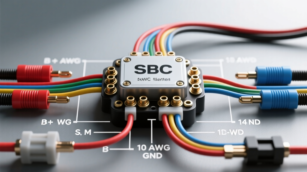
Decoding the SBC Starter Wiring Diagram
The Small Block Chevrolet (SBC) is arguably the most ubiquitous V8 engine in automotive history. Whether you are restoring a 1969 Camaro, wiring a 1972 C10 pickup, or building a Pro-Touring hot rod, understanding the SBC starter wiring diagram is a fundamental rite of passage. While the Gen I SBC (1955–2003) starter circuit appears simple on the surface, improper wiring, incorrect wire gauges, or misunderstood ignition bypass circuits frequently lead to voltage drops, heat soak, and catastrophic component failure.
This complete wiring walkthrough dissects the classic Delco-Remy style starter solenoid, details the exact AWG requirements, explains the often-misunderstood "I" terminal bypass, and provides actionable solutions for common SBC starting ailments. For authoritative standards on automotive electrical loads, we reference the SAE J1292 Electrical Systems Standard and historical GM service documentation.
Visualizing the SBC Starter Circuit Architecture
Before cutting or crimping any wire, you must understand the flow of current through the classic SBC starter solenoid. The solenoid acts as both a heavy-duty relay (closing the circuit between the battery and the starter motor) and a mechanical actuator (throwing the Bendix drive pinion gear into the flexplate ring gear).
The Three Solenoid Terminals Explained
- BAT (Battery) Terminal: The large 3/8-inch threaded stud closest to the engine block. This receives constant 12V+ from the battery and feeds the internal starter motor windings once the solenoid plunger is pulled inward.
- S (Start) Terminal: The smaller inner spade terminal. This receives the 12V+ trigger signal from the ignition switch's "Start" position (often routed through a neutral safety switch or clutch interlock). Energizing this terminal pulls the solenoid plunger.
- I (Ignition) Terminal: The smaller outer spade terminal. This is a switched 12V+ output that only provides power while the solenoid is fully engaged. It is used strictly to bypass the ballast resistor in points-style ignition systems during cranking.
Wire Gauge (AWG) and Color Code Specifications
Using undersized wiring is the number one cause of slow-cranking SBCs. Copper Clad Aluminum (CCA) wire should be avoided entirely; always use Oxygen-Free High Thermal Conductivity (OFHC) pure copper. Below is the specification chart for a standard Gen I SBC starter circuit.
| Circuit Path | AWG Size | GM OEM Color Code | Function | Torque Spec |
|---|---|---|---|---|
| Battery (+) to BAT Terminal | 1/0 AWG or 2 AWG | Red (or Unjacketed) | Main high-amperage current feed (200A-400A peak) | 8-11 Nm (75-100 in-lbs) |
| Ignition Switch to S Terminal | 10 AWG or 12 AWG | Purple | Solenoid trigger signal (approx. 30A inrush) | N/A (Push-on Spade) |
| I Terminal to Coil (+) | 14 AWG or 16 AWG | Yellow (or Resistance Wire) | Ignition ballast bypass during cranking | N/A (Push-on Spade) |
| Battery (-) to Engine Block | 1/0 AWG or 2 AWG | Black | Main ground return path | 25-35 ft-lbs (Block Bolt) |
| Engine Block to Chassis | 10 AWG or 8 AWG | Black / Braided Strap | Ensures block-to-frame continuity | 15 ft-lbs |
Note: Over-torquing the BAT terminal nut is a common rookie mistake. The solenoid cap is made of brittle Bakelite or phenolic resin. Exceeding 100 in-lbs will crack the cap, leading to moisture ingress and internal shorting.
Step-by-Step Wiring Walkthrough
1. Main Battery Feed (BAT Terminal)
Route a 1/0 AWG pure copper cable from the battery positive terminal to the starter BAT terminal. If your battery is relocated to the trunk (common in hot rods and Pro-Touring builds), the increased cable length creates significant voltage drop. In trunk-mount scenarios, upgrading to a 2/0 AWG cable is mandatory to maintain adequate cranking amperage. Always use adhesive-lined marine-grade heat shrink on your ring terminals to prevent corrosion at the crimp joint.
2. Ignition Trigger Circuit (S Terminal)
The S terminal requires a 10 AWG or 12 AWG wire (traditionally Purple in GM harnesses). This wire runs from the ignition switch's "Crank" terminal, through the firewall bulkhead connector, and down to the starter. Crucial Integration: If your vehicle is an automatic, this wire must be routed through the steering column or console-mounted Neutral Safety Switch (NSS). The NSS ensures the starter only engages when the transmission is in Park or Neutral. For manual transmissions, route this circuit through a clutch pedal interlock switch for safety.
3. The Ignition Bypass Circuit (I Terminal)
This is where most SBC wiring errors occur. The "I" terminal was designed specifically for points-style distributors. Because points ignitions use a ballast resistor wire (typically 1.2 to 1.8 ohms) to lower running voltage and prevent coil saturation, the spark would be too weak during cranking when system voltage drops to 9V-10V. The "I" terminal sends a full 12V+ directly to the coil's positive terminal only while the starter is engaged, bypassing the resistor.
WARNING: If your SBC is equipped with a GM HEI (High Energy Ignition) distributor, an MSD capacitive discharge box, or modern EFI, do not connect anything to the "I" terminal. HEI and MSD systems require a full 12V+ at all times. Feeding 12V from the "I" terminal back into an HEI harness can backfeed voltage, fry ignition modules, or prevent the engine from shutting off when the key is turned to the "Off" position. For comprehensive HEI and MSD integration details, consult the MSD Ignition Application Notes.
Common SBC Starter Failure Modes & Troubleshooting
Use this diagnostic decision tree to troubleshoot SBC starting issues based on the auditory and electrical symptoms presented at the key switch.
| Symptom | Probable Cause | Diagnostic Fix / Action |
|---|---|---|
| Single Loud "Clack" (No Crank) | Severe voltage drop on main cables or poor engine ground. | Perform a voltage drop test across the BAT cable and ground strap under load. Clean block-to-chassis ground mating surfaces to bare metal. |
| High-Pitched Whining / Grinding | Improper starter nose cone shimming; pinion gear binding on flexplate. | Check flexplate tooth count (153 vs 168). Install 0.015" to 0.030" shims on the starter mounting bolts to adjust gear mesh depth. |
| Starter Stays Engaged | Solenoid contacts internally welded together, or S-wire shorted to 12V. | Disconnect Purple S-wire. If starter still engages, replace solenoid. If it stops, trace S-wire for chafed insulation shorting against exhaust/header. |
| Heat Soak (Clicks when hot, cranks cold) | Exhaust header heat transferring into the solenoid coil, increasing resistance. | Install a ceramic-coated heat shield, wrap headers, or convert to a gear-reduction mini starter. |
Solving Heat Soak: The Remote Solenoid Conversion
The classic SBC starter is notorious for "heat soak." Because the starter is mounted low and close to the exhaust manifolds or headers, radiant heat bakes the solenoid coil. As the copper windings inside the solenoid heat up, electrical resistance increases. Eventually, the 12V trigger from the S terminal cannot generate enough magnetic force to pull the plunger, resulting in a rapid clicking or a single dead click when the engine is hot.
The Pro Fix: Hot rod builders frequently utilize a Ford-style remote starter solenoid mounted high on the firewall or inner fender, away from exhaust heat. Wiring the Remote Conversion: 1. Run 1/0 AWG from the Battery (+) to the remote solenoid's main input stud. 2. Run 1/0 AWG from the remote solenoid's output stud to the SBC starter's BAT terminal. 3. Connect the ignition switch's Purple S-wire to the remote solenoid's "S" spade. 4. Critical Step: Install a heavy-gauge jumper wire directly between the SBC starter's BAT terminal and its "S" terminal. This ensures that when the remote solenoid sends power down to the engine bay, the SBC starter's internal solenoid is instantly bypassed and engaged, throwing the Bendix gear while the remote solenoid handles the heavy amperage load. This setup virtually eliminates heat soak and is a staple in high-performance SBC builds.
Upgrading to a High-Torque Mini Starter
If you are running a high-compression SBC (11.0:1 or higher) or a large camshaft with high cranking cylinder pressures, the stock 1.4kW Delco starter will struggle. Upgrading to a gear-reduction mini starter (such as those from Powermaster or MSD) provides 3.0kW to 4.0kW of cranking power while reducing physical size and weight.
When wiring a mini starter, the basic SBC starter wiring diagram remains identical (BAT, S, and I terminals). However, pay strict attention to the mounting bolt pattern. SBC blocks feature two starter bolt holes: an inner and an outer.
- 153-Tooth Flexplate: Requires a starter with a straight-across bolt pattern.
- 168-Tooth Flexplate: Requires a starter with a staggered (diagonal) bolt pattern.
Conclusion
Mastering the SBC starter wiring diagram requires more than just connecting a battery cable and a trigger wire. By respecting AWG sizing limits, understanding the specific application of the "I" terminal bypass, ensuring robust engine grounding, and addressing thermal management via remote solenoids or mini starters, you guarantee reliable, high-amperage cranking for your Small Block Chevy. For further reading on classic GM bulkhead connector routing and grounding methodologies, refer to the Haynes Tech Tutorials archive.