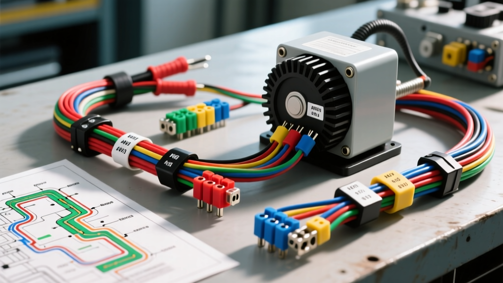
Introduction: Powering Automotive Shops, Mobile Service Trucks, and EV Benches
When outfitting a custom automotive restoration shop, a heavy-duty mobile service truck (such as a Ford F-550 or Freightliner M2 walk-in body), or an EV conversion garage, single-phase power is rarely enough. Running 3-phase automotive lifts, heavy-duty onboard hydraulic cranes, or EV powertrain test dynos (like a salvaged Tesla Model 3 Large Drive Unit) requires a robust phase conversion system. Reviewing a precise wiring diagram for rotary phase converter setups is the first step in bridging the gap between standard 240V single-phase supply and the 3-phase 240V demand of industrial automotive equipment.
However, misinterpreting these schematics leads to catastrophic failures, blown contactors, and severe electrical hazards. This guide breaks down the critical safety warnings, common wiring mistakes, and exact AWG specifications required when integrating rotary phase converters into automotive and heavy-duty mobile environments.
Critical Safety Warnings Before You Wire
Working with 240V AC systems and idler motors introduces unique hazards that standard 12V automotive wiring does not. Before consulting your schematic, internalize these non-negotiable safety rules:
- The 'Generated Leg' Hazard: In a rotary phase converter, the third leg (L3 or T3) is 'generated' by the idler motor's back-EMF. If the idler motor spins without a load connected to L3, the voltage on this leg can spike to over 300V-350V. Never probe L3 with standard automotive multimeters rated only for CAT II; use a CAT III or CAT IV rated meter.
- Capacitor Discharge Risks: Start and run capacitors store lethal DC voltages even after the main breaker is thrown. Always use a 20k-ohm, 5-watt bleeder resistor across the capacitor terminals before touching any wiring.
- Chassis vs. Earth Grounding: In mobile service trucks, the vehicle chassis is often used as a DC ground. The AC grounding conductor (Green/Bare) from the phase converter MUST be bonded to a dedicated earth ground rod or the truck's dedicated AC grounding bus, never to the 12V/24V DC chassis ground. Mixing AC and DC grounds will destroy sensitive automotive diagnostic tools and EV battery management systems (BMS).
Deconstructing the Wiring Diagram for Rotary Phase Converter
A standard automotive shop rotary phase converter schematic is divided into three primary circuits: the Single-Phase Input, the Idler Motor Circuit, and the Three-Phase Output.
1. Single-Phase Input (L1 & L2)
Power enters from the main breaker panel or the mobile truck's onboard PTO-driven AC generator. According to NEC Article 455, the input disconnect must be a fused switch rated for the full locked-rotor current of the idler motor. Standard wire colors for 240V single-phase input are Black (L1) and Red (L2).
2. The Idler Motor and Capacitor Bank
The idler motor is a standard 3-phase induction motor. The wiring diagram routes L1 and L2 to the motor's T1 and T2 terminals. To start the motor, a start capacitor bank is wired in parallel with a potential relay. Once the idler reaches roughly 75% of its rated RPM, the potential relay's normally-closed (NC) contacts open, dropping the start capacitors from the circuit while leaving the run capacitors engaged to balance the voltage.
3. Three-Phase Output (L1, L2, L3)
The output terminals feed your automotive equipment (e.g., a BendPak 3-phase lift motor or an EV dyno inverter). The wire colors transition here: Black (L1), Red (L2), and Blue (L3 - Generated). The generated leg (Blue) must be clearly marked with orange phase tape at every junction box to warn future technicians.
Common Mistakes & Troubleshooting Decision Tree
Even experienced automotive electricians make errors when transitioning from low-voltage DC to high-voltage 3-phase AC. Use this decision tree to diagnose common phase converter issues:
- Symptom: Idler motor hums loudly but fails to start.
Cause: Failed start capacitor or stuck potential relay.
Fix: Test start capacitors for microfarad (uF) degradation. Verify the potential relay coil voltage matches the generated leg voltage. - Symptom: EV test bench motor runs hot and vibrates under load.
Cause: Severe voltage imbalance on L3.
Fix: Adjust the run capacitor bank. You typically need 15-20 uF of run capacitance per horsepower of the idler motor to balance the generated leg within 5% of L1 and L2. - Symptom: Lift limit switches or 120V control circuits burn out instantly.
Cause: The 'Generated Leg' Mistake.
Fix: The 120V control circuits were wired between L1 and L3, or L2 and L3. Never use the generated Blue leg (L3) for any 120V single-phase control circuits. Always derive 120V control power strictly from L1 to Neutral or L2 to Neutral.
Wire Sizing & AWG Specifications for Automotive Applications
Undersized wiring causes voltage drop, which prevents the idler motor from reaching the RPM required to open the potential relay. This results in the start capacitors remaining in the circuit, leading to explosive capacitor failure. Below is the required copper AWG sizing based on the idler motor HP and 240V input.
| Idler Motor HP | Max Input Amps | Min Copper AWG (Input L1/L2) | Min Copper AWG (Output L1/L2/L3) | Breaker Size (Time-Delay) |
|---|---|---|---|---|
| 5 HP | 28A | 8 AWG | 10 AWG | 40A |
| 10 HP | 50A | 4 AWG | 6 AWG | 70A |
| 15 HP | 75A | 2 AWG | 4 AWG | 100A |
| 20 HP | 100A | 1/0 AWG | 2 AWG | 125A |
Note: For mobile service trucks running long cable reels to external automotive lifts, increase wire gauge by one size for every 50 feet of cable to mitigate voltage drop, adhering to SAE J1171 guidelines for heavy-duty and mobile electrical environments.
Integration with EV Powertrain Test Benches
In the modern EV conversion and diagnostic space, rotary phase converters are frequently used to power the heavy 3-phase AC motors found in salvage drivetrains (such as the Cascadia Motion or Bosch eAxle systems) during bench testing. When wiring a phase converter to an EV test bench inverter, the 3-phase output must pass through a heavy-duty, 3-pole contactor controlled by the bench's safety E-stop circuit.
Furthermore, the grounding scheme must be impeccable. EV inverters utilize high-frequency PWM switching that generates severe common-mode noise. If the phase converter's ground bus is not bonded to the test bench's chassis with a minimum 6 AWG green grounding strap, this noise will induce voltage spikes in the low-voltage CAN bus lines, causing communication faults between the inverter and the diagnostic laptop.
Final Inspection and Energization Protocol
Before closing the main disconnect, verify the following checklist:
- All wire lugs are torqued to the manufacturer's specifications (typically 35-45 in-lbs for 10-8 AWG, and up to 120 in-lbs for 2 AWG).
- The generated leg (Blue) is isolated from all 120V control transformers.
- The idler motor spins freely by hand, and the potential relay is mounted in the correct orientation (some relays are gravity-sensitive).
- Earth ground continuity is verified from the converter chassis to the main grounding electrode.
For further technical specifications regarding 3-phase automotive lift installations, always cross-reference the BendPak installation manuals to ensure the phase converter's output matches the motor's nameplate voltage and frequency requirements. Proper execution of your wiring diagram guarantees a safe, balanced, and reliable power supply for the most demanding automotive machinery.