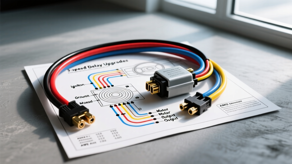
Modernizing Classic Visibility: The Case for Wiper System Upgrades
When restoring or modifying a classic vehicle from the 1950s through the 1970s, the original equipment manufacturer (OEM) electrical systems often fall short of modern safety and convenience standards. A prime example is the windshield wiper system. Many classic cars left the factory with rudimentary single-speed or two-speed wiper motors that lack an intermittent delay feature. Driving in light mist or drizzle with a single-speed motor means constantly toggling the dashboard switch, which is both distracting and dangerous.
Upgrading to a modern, universal 3-speed wiper motor with an integrated park switch and adding an aftermarket intermittent delay module drastically improves visibility and driver focus. However, executing this modification requires a precise understanding of the electrical architecture. This comprehensive wiper motor wiring diagram guide will walk you through the pinout configurations, relay logic, wire gauge sizing, and real-world troubleshooting required to successfully integrate a modern wiper system into a classic chassis.
Decoding the Universal 3-Speed Wiper Motor Wiring Diagram
Most universal 3-speed wiper motors used in classic car restorations are based on the ubiquitous General Motors (GM) column-mount or firewall-mount designs produced from the late 1960s through the 1990s. These motors utilize a 5-pin rectangular Weather-Pack connector. Understanding this connector is the foundation of your upgrade project.
The internal architecture of the motor features two separate brushes (low speed and high speed) and a mechanical park switch. The park switch is a set of internal contacts that maintains power to the low-speed brush circuit even after the dashboard switch is turned to the 'Off' position. Once the wiper arms reach the base of the windshield cowl, a cam breaks the park circuit, cutting power and ensuring the wipers stop at the bottom of their stroke.
5-Pin Weather-Pack Connector Specifications
When building your custom harness, you must use the correct terminals to prevent voltage drop and moisture intrusion. For GM-style 5-pin connectors, utilize Delphi male terminals (Part #12048025) and a Delphi Weather-Pack crimping tool (Part #12094270) to ensure a factory-grade gas-tight crimp.
| Pin Position | Function | Standard OEM Wire Color | Wire Gauge (AWG) |
|---|---|---|---|
| Pin A | Motor Ground | Black | 12 AWG |
| Pin B | Low Speed Power | Dark Blue | 14 AWG |
| Pin C | High Speed Power | Light Blue | 14 AWG |
| Pin D | Park Switch Feed | Grey | 14 AWG |
| Pin E | Washer Pump Power | Purple | 16 AWG |
Integrating an Intermittent Wiper Delay Module
To achieve variable intermittent wiper speeds, you must introduce a solid-state delay controller between your dashboard switch and the wiper motor. Popular upgrade kits, such as those from Painless Performance or Detroit Speed, utilize an 8-pin delay module that intercepts the switch inputs and pulses the low-speed circuit based on a potentiometer dial mounted on your dashboard.
Wiring the Delay Controller
The delay module requires a constant 12V source to maintain its internal timer memory, a switched 12V source to wake the module, and a direct path to the motor's park switch to know when to cut power. Miswiring the park sense wire (Pin 6) is the most common cause of wipers stopping mid-windshield during an upgrade.
| Module Pin | Function | Connection Point | Wire Color |
|---|---|---|---|
| 1 | Constant 12V Battery | Fused Battery Bus | Red |
| 2 | Chassis Ground | Clean Firewall Stud | Black |
| 3 | Switched 12V (Ignition) | Fuse Box IGN Terminal | White |
| 4 | Low Speed Output | Wiper Motor Pin B | Dark Blue |
| 5 | High Speed Output | Wiper Motor Pin C | Light Blue |
| 6 | Park Sense Input | Wiper Motor Pin D | Grey |
| 7 | Washer Switch Input | Dashboard Wiper Switch | Purple |
| 8 | Washer Pump Output | Wiper Motor Pin E | Yellow |
Wire Gauge (AWG) Sizing and Circuit Protection
Wiper motors draw significant current, particularly under high-friction loads such as moving across dry glass or clearing heavy, wet snow. While the running current of a standard 3-speed wiper motor is typically between 6 and 10 amps, the stall current (the moment the motor starts or encounters severe resistance) can spike to 15 or even 20 amps. Adhering to the SAE J1128 Low Tension Primary Cable Standard is critical for selecting the correct wire insulation and gauge.
Circuit Protection and AWG Sizing Chart
Never rely on the vehicle's original 1960s-era glass fuses or un-fused bulkhead connectors for an upgraded wiper system. Install a dedicated modern ATO blade fuse panel for the wiper circuit.
| Circuit Segment | Recommended AWG | Fuse Rating | Notes |
|---|---|---|---|
| Main Battery Feed to Delay Module | 12 AWG | 20A ATO Blade | Keep run length under 4 feet to minimize voltage drop. |
| Delay Module to Motor (Low/High) | 14 AWG | Protected by Main | Use cross-linked polyethylene (XLPE) insulation for engine bay heat. |
| Washer Pump Feed | 16 AWG | 10A ATO Blade | Washer pumps draw roughly 3-5 amps; 16 AWG is sufficient. |
| Motor Ground Path | 12 AWG | N/A | Must ground directly to the engine block or clean chassis steel. |
Real-World Troubleshooting for Upgraded Wiper Systems
Even with a flawless wiper motor wiring diagram, physical installation variables can cause operational failures. Below are the most common failure modes encountered during classic car wiper upgrades and how to diagnose them using a digital multimeter (DMM).
Symptom: Wipers Fail to Park and Stop Mid-Windshield
Cause: This is almost always a failure in the park sense circuit. The delay module relies on the grey wire (Pin D) to tell it when the motor has completed its sweep. If the internal park switch contacts are corroded, or if the grey wire has a poor connection, the module cuts power instantly when you turn the switch off, rather than waiting for the cam to break the circuit.
Fix: Disconnect the 5-pin connector at the motor. Turn the ignition to 'ON'. Use your DMM to check for 12V at the motor's Pin D terminal (the male pin on the motor side). If you have 12V, the internal park switch is functional, and the fault lies in the grey wire running back to the delay module. If you read 0V, the internal park switch is faulty, and the wiper motor must be rebuilt or replaced.
Symptom: Wipers Move Sluggishly or Stall on Dry Glass
Cause: Severe voltage drop on either the power feed or the ground circuit. Wiper motors are highly sensitive to voltage drops; operating below 11.0V under load will cause a noticeable drop in torque and speed.
Fix: Perform a loaded voltage drop test. Turn the wipers on high speed. Place your DMM's positive lead on the battery positive terminal and the negative lead on the wiper motor casing. A reading higher than 0.5V indicates a poor ground. Scrape away paint, rust, and undercoating at the motor mounting bracket, and apply dielectric grease to the bolts to prevent future corrosion. Next, test the power side by placing the positive lead on the motor's power pin and the negative lead on the battery negative terminal. Again, a drop greater than 0.5V requires upgrading the wire gauge or cleaning the firewall bulkhead connectors.
Symptom: Washer Pump Runs Continuously
Cause: A short to ground on the washer switch input wire (Pin 7 on the delay module), or a stuck internal contact within the dashboard wiper switch itself.
Fix: Unplug the delay module. If the pump stops, the module is receiving a false 'on' signal. Check the purple wire running to the dashboard switch for chafing against the metal steering column. For detailed switch continuity testing, refer to the specific chassis wiring schematics available through Helm Incorporated GM Service Manuals.
Final Modification Best Practices
When routing your new wiper motor harness through the firewall, always use a rubber grommet and secure the wiring with adhesive-lined heat shrink tubing to prevent moisture wicking into the cabin. Label all wires at both the motor and module ends using heat-shrink wire labels. A properly executed wiper motor upgrade not only modernizes your classic car's functionality but also ensures the electrical system remains safe, reliable, and easy to troubleshoot for decades to come.