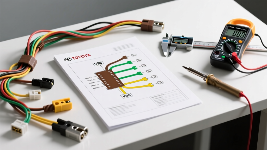
Understanding the Toyota 3-Wire Speed Sensor Architecture
When diagnosing a faulty vehicle speed sensor (VSS) on 1996 through 2005 Toyota trucks and SUVs (such as the Tacoma, 4Runner, and T100), accessing an accurate toyota 3 wire speed sensor wiring diagram pdf is only the first step in a successful repair. Unlike older 2-wire variable reluctance (VR) sensors that generate an alternating current (AC) sine wave based on magnetic reluctance, Toyota's 3-wire VSS utilizes a solid-state Hall-effect design. This architecture requires a dedicated power supply, a clean chassis or sensor ground, and a digital square-wave signal output wire.
Misinterpreting the factory wiring schematic or using inadequate diagnostic tools frequently leads to misdiagnosed powertrain control module (PCM) failures, damaged 5V reference circuits, or wasted capital on unnecessary OEM sensors. This comprehensive guide breaks down the exact tool requirements, cost analysis, and technical specifications needed to execute a flawless VSS circuit repair, ensuring you do not throw expensive parts at a simple wiring fault.
Decoding the Toyota 3-Wire Hall-Effect VSS Pinout
Before purchasing tools or replacement pigtails, you must understand the circuit topology. The 3-wire Hall-effect sensor acts as an open-collector switch. The PCM or instrument cluster provides a 5V pull-up reference, and the sensor pulls this voltage to ground as the transmission output shaft rotates, creating a digital square wave. Below is the standard pinout configuration for Toyota's OBD2-era 3-wire VSS.
| Pin | Function | Typical Wire Color | Wire Gauge (AWG) | Voltage / Spec |
|---|---|---|---|---|
| 1 | VCC / IG (Power) | Black/Yellow or White/Red | 20 AWG (0.5 mm²) | 5.0V Reference (OBD2) or 12V (Pre-96) |
| 2 | SPD (Signal Output) | White or Blue | 20 AWG (0.5 mm²) | 0V to 5V Square Wave (4 pulses/rev) |
| 3 | E1 (Sensor Ground) | Brown/Black or Solid Brown | 20 AWG (0.5 mm²) | < 0.5 Ohms to PCM/Battery Ground |
Note: Always verify wire colors against your specific factory service manual, as mid-year production changes and harness revisions can alter jacket colors. Rely on pin position and continuity testing rather than visual color matching alone.
Diagnostic Tool Requirements & Cost Analysis
Testing a Hall-effect sensor requires tools capable of reading rapid DC voltage switching and verifying circuit integrity under load. A standard test light will not work and can short the 5V reference circuit, potentially destroying the PCM's internal voltage regulator. Below is a cost breakdown of the required diagnostic equipment.
Essential Diagnostic Tool Budget
| Tool / Equipment | Purpose | Estimated Cost (USD) | Necessity Level |
|---|---|---|---|
| Digital Multimeter (DMM) with Min/Max | Verify 5V reference, ground continuity, and average signal voltage. | $50 - $150 | Mandatory |
| Automotive Backprobe Pins (T-Pins) | Access connector terminals without spreading or damaging weather seals. | $15 - $25 | Mandatory |
| Digital Storage Oscilloscope (DSO) | Visualize square wave duty cycle, identify signal dropouts under load. | $250 - $500+ | Highly Recommended |
| Breakout Box / Harness Jumper | Test sensor while connected and spinning the output shaft. | $30 - $60 | Optional |
According to Fluke Automotive Diagnostics, utilizing a DMM with a Min/Max record function is critical for Hall-effect sensors. Because the sensor switches between 0V and 5V rapidly, a standard DMM sampling rate might only display an average voltage of 2.5V. The Min/Max function captures the true peak and floor voltages, confirming the sensor is fully pulling the signal to ground and releasing it to 5V.
Sourcing the Wiring Diagram: OEM vs. Aftermarket PDF Costs
One of the most significant hidden costs in automotive electrical repair is acquiring accurate documentation. Searching for a free 'toyota 3 wire speed sensor wiring diagram pdf' on aftermarket forums often yields outdated, mislabeled, or low-resolution schematics that omit crucial splice locations and ground distribution points (e.g., Ground point E1 or IE1).
- Toyota TechInfo Subscription: For $20 (2-day access) or $80 (annual), you can download factory OEM wiring diagram PDFs directly from Toyota TechInfo. This is the most cost-effective route for professional-grade accuracy, ensuring you have the exact harness routing and connector cavity views.
- Haynes / Chilton Manuals: Physical or digital aftermarket manuals typically cost $30 to $50. While they provide basic pinouts, they often lack the detailed ground distribution charts and splice pack locations required for deep harness repairs.
- Dealership Parts Counter: Some dealerships will print a 2-page wiring schematic for free or a nominal printing fee if you provide the VIN and request the specific circuit (e.g., 'Speed Sensor Circuit').
Executing the Repair: Wire Gauge, Splicing, and Connector Costs
If your diagnostic testing reveals high resistance, capillary corrosion, or broken strands within the VSS harness, executing a proper repair requires adherence to SAE J1128 Low Tension Cable Standards. The Toyota VSS harness utilizes 20 AWG (0.5 mm²) cross-linked polyethylene (XLPE) or PVC jacketed wire. Using thicker 16 AWG wire for repairs will cause terminal spread inside the Sumitomo HM-series connector, leading to intermittent connection loss due to vibration.
Material Cost Breakdown for Harness Repair
- OEM Pigtail Assembly (Part #90980-11019 or similar): $25 - $45. Always buy the pigtail with pre-crimped terminals and sealed wires. Never attempt to crimp aftermarket unsealed terminals into a waterproof sensor connector.
- Solder Seal Wire Connectors (20-24 AWG): $15 for a kit. These provide a waterproof, vibration-resistant splice that meets OEM standards when heat-shrunk properly.
- Silicone Dielectric Grease: $8. Essential for packing the rear of the connector cavity to prevent moisture ingress and terminal oxidation.
Expert Warning: The most common failure mode on Toyota truck VSS connectors is not the sensor itself, but the degradation of the silicone weather pack seals inside the 3-way connector. When these seals crack, water wicks into the wire insulation via capillary action, traveling up the harness and corroding the PCM pins. If you see green crust on the sensor terminals, you must cut the harness back at least 12 inches to remove the oxidized copper.
Troubleshooting Decision Tree: No-Speed Signal (P0500)
Follow this logical sequence when the speedometer is inoperative, the transmission shifts erratically, and a P0500 (Vehicle Speed Sensor Malfunction) code is stored. This tree assumes you have the wiring diagram PDF in hand and your DMM is ready.
Step 1: Verify the Power Circuit (Pin 1)
- Action: Backprobe Pin 1 with the ignition ON, engine OFF (KOEO).
- Expected Result: 4.8V to 5.2V (or 12V on pre-OBD2 models).
- Failure Mode A (0V): Open circuit between PCM and sensor, or blown PCM internal 5V regulator. Check for short-to-ground on the signal wire before condemning the PCM.
- Failure Mode B (2.5V): The 5V reference is being pulled down. Disconnect the sensor. If voltage returns to 5V, the sensor is internally shorted. If it stays at 2.5V, the harness is shorted to ground or another sensor on the same 5V reference bus is faulty.
Step 2: Verify the Ground Circuit (Pin 3)
- Action: Measure resistance between Pin 3 and the battery negative terminal.
- Expected Result: Less than 0.5 Ohms.
- Failure Mode (High Resistance / OL): Corroded ground splice or broken wire. Do not run a new ground directly to the engine block; the PCM must control the sensor ground to prevent ground loop interference with the signal wave.
Step 3: Verify the Signal Circuit (Pin 2)
- Action: Backprobe Pin 2. Set DMM to DC Volts. Safely raise the vehicle, start the engine, and place the transmission in Drive (wheels off the ground).
- Expected Result: The DMM should read an average of 2.2V to 2.8V, fluctuating slightly as the sensor switches.
- Failure Mode (Stuck at 5V): Open circuit in the signal wire between the sensor and PCM, or the sensor is dead and not pulling the circuit to ground.
- Failure Mode (Stuck at 0V): Signal wire is shorted to chassis ground, or the sensor's internal transistor is shorted.
By combining the precise data from a factory Toyota wiring diagram PDF with the correct diagnostic tools and OEM-specification repair materials, you can confidently isolate and repair 3-wire VSS faults without resorting to unnecessary parts replacement. Always prioritize circuit integrity and terminal tension over simply swapping the sensor.