Navigating the 2004 Silverado Wiring Diagram PDF Landscape
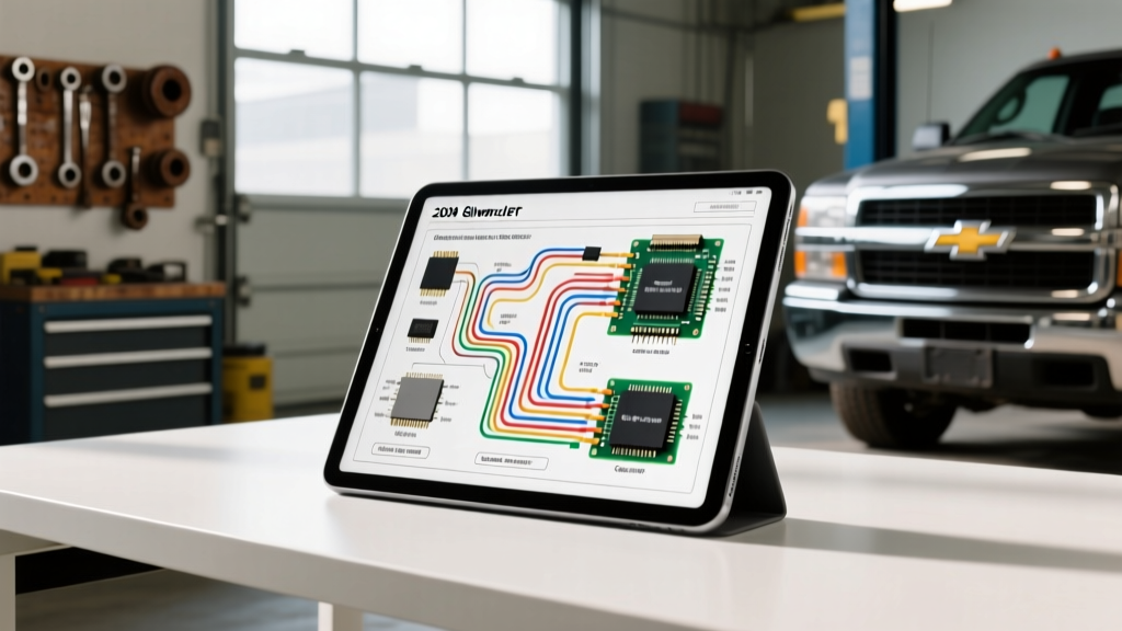
When searching for a comprehensive 2004 silverado wiring diagram pdf, technicians and DIYers often hit a wall. Factory service manuals (FSM) are fragmented across hundreds of pages, and generic aftermarket schematics frequently omit critical splice pack locations, exact AWG wire gauges, and module-specific pinout matrices. The 2004 Chevrolet Silverado represents a pivotal year in the GMT800 platform's electrical evolution. It sits at the intersection of legacy high-current routing and early multiplexed data networks. To properly diagnose no-start conditions, parasitic draws, or communication faults, you must understand the underlying architecture rather than just tracing lines on a flat PDF.
This advanced technical deep dive bypasses the fluff and provides the exact PCM pinout configurations, Class 2 Serial Data topology, and high-current failure modes that define the 2004 Silverado's electrical system. Whether you are troubleshooting a 5.3L V8 (LM7/L33) or a 6.0L V8 (LQ4), the core electrical principles and connector matrices remain consistent across the GMT800 light-duty lineup.
PCM Connector Matrix: C1, C2, and C3 Pinouts
The 2004 Silverado utilizes a Delphi-designed Powertrain Control Module (PCM) featuring a three-connector layout. Unlike the earlier 1999-2002 two-connector (Blue/Red) setups, the 2004 P59/E40 generation PCM uses an 80-pin Black connector (C1), an 80-pin Red connector (C2), and a 40-pin Gray connector (C3) for specific sensor and actuator circuits. Understanding these pinouts is critical when performing bench flashes, parasitic draw tests, or diagnosing injector driver faults.
| Connector | Pin | Circuit Function | Wire Color | AWG / Notes |
|---|---|---|---|---|
| C1 (Black) | 1 | Injector 1 Control | Dark Green/White | 18 AWG (Saturation/Off driver) |
| C1 (Black) | 21 | Crankshaft Position (CKP) Signal | Yellow | 20 AWG (Shielded) |
| C1 (Black) | 36 | Ignition 1 Voltage Feed | Pink | 16 AWG (Switched 12V) |
| C2 (Red) | 41 | Battery Positive Voltage | Red | 12 AWG (Constant 12V) |
| C2 (Red) | 68 | Class 2 Serial Data | Dark Green | 20 AWG (VPW Network) |
| C2 (Red) | 73 | PCM Ground | Black/White | 12 AWG (Engine Block) |
| C3 (Gray) | 1 | MAF Sensor Signal | Yellow | 20 AWG (Frequency output) |
| C3 (Gray) | 12 | Fuel Pump Relay Control | Dark Green/White | 18 AWG (Low-side driver) |
| C3 (Gray) | 24 | Camshaft Position (CMP) Signal | Tan/Black | 20 AWG (1x per cam rev) |
Class 2 Serial Data Bus: Topology and Diagnostics
Before GM fully adopted the high-speed CAN-bus (GMLAN) architecture in later GMT900 models, the 2004 Silverado relied on the SAE J1850 Variable Pulse Width (VPW) standard, commonly referred to as Class 2 Serial Data. This single-wire network operates at 10.4 kbps and allows the PCM, Body Control Module (BCM), Instrument Panel Cluster (IPC), and Electronic Brake Control Module (EBCM) to share critical operating parameters.
The SP205 Splice Pack Vulnerability
In a 2004 silverado wiring diagram pdf, you will see the Class 2 bus routed through various modules. However, the physical star-topology hub for this network is Splice Pack 205 (SP205). Located under the driver's side carpet near the left kick panel, SP205 is a multi-port connector that joins the Dark Green Class 2 wires from the PCM, BCM, DLC (Pin 2), and other modules.
- Failure Mode: Water intrusion from a leaking door seal, clogged AC evaporator drain, or aftermarket windshield installation causes the SP205 terminals to corrode.
- Symptom: Intermittent U1000 (Class 2 Communication Malfunction) DTCs, erratic fuel gauge readings, and 'Service Engine Soon' illumination.
- Diagnostic Fix: Pull back the carpet, disconnect SP205, and inspect for green crusties. Do not simply pierce the wire with a test light; use a high-impedance DMM to check for the 7V resting bias voltage on the Dark Green circuit with the key ON, engine OFF.
Critical High-Current Failure Modes in the GMT800
While data networks cause communication headaches, the high-current 12V routing in the 2004 Silverado is responsible for the majority of catastrophic electrical failures. The wiring diagrams reveal several design compromises that technicians must proactively address.
1. Ignition Switch Harness Meltdown
The GMT800 ignition switch routes massive electrical loads directly through the switch contacts on the steering column. According to Haynes technical service bulletins, the primary ignition feed (Pink, 12 AWG) and the main battery feed (Red, 10 AWG) are subjected to extreme thermal cycling. The HVAC blower motor and rear defogger circuits pull significant amperage through these pathways. Over time, the resistance at the switch terminals increases, generating enough heat to melt the plastic connector housing and fuse the wires together. If your 2004 Silverado experiences random stalling, loss of dash illumination, or a melted smell under the dash, inspect the ignition switch pigtail immediately and upgrade the harness using a heavy-duty repair kit with 10 AWG pigtails.
2. Underhood B-Junction Block Corrosion
Located near the master cylinder on the driver's side firewall, the B-Junction Block (often labeled as the Underhood Electrical Center or UHEC auxiliary block) distributes battery power to the PCM, fuel pump relay, and ABS module. The factory seal on the top cover degrades due to UV exposure and engine bay heat. When water enters the block, it creates galvanic corrosion between the heavy-gauge copper bus bars and the aluminum terminals. This results in severe voltage drops at the PCM (C2 Pin 41) and fuel pump relay, leading to extended cranking times or random fuel pump cutouts at highway speeds.
Sensor Circuit Deep Dive: CKP and MAF
When diagnosing driveability issues, referencing the exact sensor circuits from the OEM schematic is mandatory. The 2004 5.3L utilizes a 3-wire Hall-effect Crankshaft Position (CKP) sensor and a 5-wire Hot-Wire Mass Air Flow (MAF) sensor with an integrated Intake Air Temperature (IAT) thermistor.
Crankshaft Position Sensor (CKP)
The CKP sensor requires a pristine 12V reference (Pink wire) and a dedicated low-reference ground (Purple/White). The signal wire (Yellow) outputs a 5V square wave. A common misdiagnosis occurs when technicians see a 'No Signal' code and replace the sensor, only to find the Purple/White low-reference wire has chafed against the engine block near the oil pan rail, shorting the 5V pull-up resistor inside the PCM.
Mass Air Flow (MAF) / IAT Sensor
The MAF signal (Yellow) outputs a frequency-based signal (Hz) rather than a traditional analog voltage. The IAT circuit uses a 5V reference (Tan) and a low-reference (Tan/Black). Because the IAT is a negative temperature coefficient (NTC) thermistor, a short to ground on the Tan signal wire will cause the PCM to read an artificially high intake temperature, resulting in aggressive timing pull and severe power loss under load.
Summary and Professional References
Relying solely on a flattened 2004 silverado wiring diagram pdf is insufficient for modern diagnostics. True mastery of the GMT800 electrical system requires understanding the physical routing of the Class 2 Serial Data bus, the thermal vulnerabilities of the ignition switch harness, and the precise pinout matrices of the Delphi PCM. Always verify wire colors against your specific RPO code build sheet, as mid-year production changes can occasionally alter secondary ground wire tracers. For further reading on multiplexed automotive networks and GM-specific diagnostic strategies, consult the SAE J1850 VPW documentation and OEM-specific connector repair manuals.