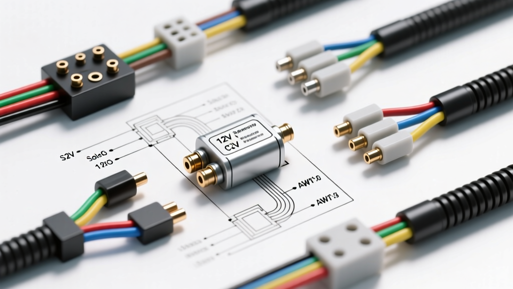
Demystifying the '1 Phase' Automotive Starter Terminology
When beginners first dive into automotive electrical repair, they often search for a 1 phase starter wiring diagram. This terminology is actually borrowed from industrial AC (Alternating Current) motor systems, where 'single-phase' refers to a specific type of power delivery. However, standard automotive electrical systems operate on 12-volt DC (Direct Current). In the automotive world, what a beginner means by a '1 phase' diagram is a single-stage, single-circuit starter engagement system.
Unlike heavy-duty commercial trucks or older complex setups that might use a two-stage series-parallel switching mechanism to crank a massive diesel engine, the standard passenger car, light truck, or SUV uses a straightforward single-stage circuit. Power flows from the battery to a solenoid, which simultaneously bridges the high-amperage motor circuit and mechanically engages the pinion gear with the flywheel. Understanding this fundamental single-stage layout is the bedrock of all automotive starting system diagnostics.
The Core Components of a Single-Stage Starter Circuit
Before tracing the wires, you must identify the primary nodes in the circuit. A standard single-stage 12V starter system consists of the following components:
- The Battery: The DC power source, ideally maintaining 12.6V at rest and no less than 9.6V during cranking.
- The Ignition Switch: The low-amperage trigger that initiates the start sequence when turned to the 'CRANK' position.
- Neutral Safety Switch (NSS) / Clutch Interlock: A safety interrupter that prevents the starter from engaging unless the transmission is in Park/Neutral or the clutch is fully depressed.
- Starter Relay (Control Module): Used in most modern vehicles to prevent the ignition switch from handling the 10-20 amp draw required to activate the starter solenoid's internal magnetic coil.
- The Starter Solenoid: The heavy-duty electromagnetic switch mounted either on the starter motor housing (common in GM and Chrysler) or on the fender well (classic Ford).
- The Starter Motor: The high-torque DC electric motor that physically rotates the engine's flywheel.
Standard 12V Starter Solenoid Terminal Pinout
The solenoid is the heart of the 1 phase starter wiring diagram. It acts as both a heavy-duty electrical relay and a mechanical actuator. Depending on the manufacturer, the solenoid will have between two and four external terminals. Below is the standard pinout configuration for a classic 4-terminal solenoid (often found on older points-ignition vehicles and universal replacement units):
| Terminal Label | Function | Internal Connection |
|---|---|---|
| B (Battery) | Receives constant 12V+ directly from the battery positive terminal via heavy-gauge cable. | Connects to the internal copper contact disc. |
| M (Motor) | Sends 12V+ to the starter motor's main field coil terminal when the solenoid engages. | Connects to the opposite side of the internal copper contact disc and the pull-in/hold-in windings. |
| S (Start/Signal) | Receives the 12V+ trigger signal from the ignition switch/start relay to energize the solenoid coil. | Connects to the internal electromagnetic pull-in and hold-in coils. |
| R / I (Resistance/Ignition) | Outputs 12V+ only during cranking to bypass the ballast resistor on older points-style ignition coils. | Connects to an internal wiper that contacts the B-terminal post only when the plunger is fully depressed. |
Note: Modern electronic fuel injection (EFI) vehicles do not use the 'R' terminal, as their ECU manages spark timing and dwell independently of the starter circuit.
Wire Gauge (AWG) and Color Code Specifications
Using the correct American Wire Gauge (AWG) is critical. The starter circuit is divided into two distinct sub-circuits: the High-Current Cranking Circuit and the Low-Current Control Circuit. According to AutoShop 101 Electrical Fundamentals, undersizing the high-current cables will result in severe voltage drop, slow cranking speeds, and melted insulation.
| Circuit Segment | Typical AWG Size | Amperage Capacity | Standard OEM Color Code |
|---|---|---|---|
| Battery (+) to Solenoid 'B' | 1/0 AWG or 2 AWG | 150A - 250A+ | Red (or Black with Red Stripe) |
| Solenoid 'M' to Motor Post | 1/0 AWG or 2 AWG | 150A - 250A+ | Red or Black (Heavy Braided) |
| Ignition/Relay to Solenoid 'S' | 12 AWG or 14 AWG | 10A - 20A | Purple (GM) / Red-Blue (Ford) |
| Solenoid 'R' to Coil (+) | 14 AWG or 16 AWG | 5A - 10A | Yellow or White |
| Engine Block to Chassis (Ground) | 1/0 AWG or 2 AWG | 150A - 250A+ | Black (Unsheathed Braided) |
Step-by-Step Wiring Walkthrough for Beginners
To properly wire or trace a single-stage starter diagram, follow the path of the electrons from the moment you turn the key:
- The Control Trigger: Turning the key to 'START' sends 12V through the Neutral Safety Switch. This low-amperage signal travels via a 14 AWG wire to the coil of the Starter Relay.
- The Relay Switch: The starter relay coil energizes, pulling its internal contacts closed. This allows battery voltage to flow from the relay's output terminal directly to the 'S' terminal on the starter solenoid.
- Solenoid Actuation: When 12V hits the 'S' terminal, the solenoid's internal magnetic coils energize. This creates a magnetic field that pulls the heavy copper plunger inward.
- Mechanical Engagement: As the plunger moves inward, a shift fork pushes the starter motor's pinion gear outward to mesh with the engine's flywheel ring gear.
- High-Current Bridge: At the very end of the plunger's travel, the copper disc bridges the 'B' and 'M' terminals. Massive current (up to 250 amps) flows from the battery, through the solenoid, and into the starter motor, spinning the engine.
Common Failure Modes and Voltage Drop Testing
When a vehicle exhibits a 'no-crank' or 'slow-crank' condition, beginners often immediately replace the starter motor. However, AA1Car Starter Circuit Diagnostics emphasizes that over 40% of starter-related complaints are actually caused by wiring faults, corroded grounds, or failing control relays. To diagnose this like a professional, you must perform a Voltage Drop Test across the high-current cables while the engine is cranking.
How to Perform a Starter Voltage Drop Test
According to SAE International Standards for automotive electrical testing, a healthy high-current cable should exhibit a voltage drop of no more than 0.1 volts per connection or cable segment under load.
- Step 1: Set your digital multimeter (DMM) to DC Volts.
- Step 2: Place the red probe on the battery positive post and the black probe on the solenoid 'B' terminal post.
- Step 3: Have an assistant crank the engine. If the DMM reads more than 0.2V, the positive battery cable is corroded internally or the terminal connections are loose.
- Step 4: Move the red probe to the solenoid 'M' terminal and the black probe to the starter motor's main casing or input post. Crank again. A reading over 0.1V indicates a failing internal solenoid contact disc.
- Step 5 (The Ground Side): Place the red probe on the starter motor casing (bare metal) and the black probe on the battery negative post. Crank the engine. A reading over 0.2V indicates a poor engine-to-chassis ground strap, which is a notoriously common failure point on older trucks and SUVs.
Upgrading to a High-Torque Mini Starter
Many enthusiasts modifying classic cars or off-road trucks upgrade from a heavy, direct-drive OEM starter to a permanent-magnet gear-reduction (PMGR) 'mini' starter. While the fundamental single-stage wiring logic remains identical, the physical installation requires specific wiring adjustments. PMGR starters draw significantly less amperage to produce the same cranking torque (often peaking around 120-150 amps compared to 250 amps for older direct-drive units). However, because mini starters are physically smaller, they sit closer to the exhaust headers. It is absolutely critical to route the 1/0 AWG battery cable away from heat sources and use high-temperature silicone wire loom. Additionally, if your mini starter features a dedicated 'S' terminal spade connector rather than a threaded stud, ensure you use a fully insulated female spade connector with a locking tab to prevent the wire from vibrating loose during heavy engine harmonics.