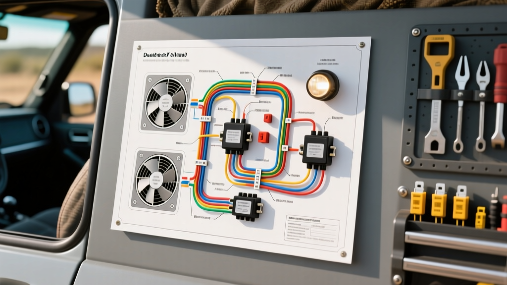
Introduction to Dual-Switch Auxiliary Circuits
When modifying a classic truck, building a rock-crawling Jeep Wrangler, or outfitting an overland SUV, managing high-draw accessories is a primary electrical challenge. Many off-roaders search for a wiring diagram for double switch for fan and light circuits to simultaneously control an auxiliary electric radiator fan (for low-speed trail crawling) and a high-output LED light bar. While this phrase often brings up residential bathroom exhaust fans, the automotive equivalent requires a completely different approach to 12V DC power management, vibration resistance, and weatherproofing.
In this beginner-friendly fundamentals guide, we will translate standard dual-switch schematics into a robust, automotive-grade wiring harness. Whether you are driving a 2018 Jeep Wrangler JK or a 1990s Chevy C10, understanding how to safely route power, utilize ISO mini relays, and select the correct SAE wire gauge is critical to preventing electrical fires and voltage drop.
Why You Cannot Wire Directly to the Switch
The most common mistake beginners make when installing a double-gang rocker switch panel is routing the full load of the fan and light bar directly through the dashboard switches. A standard 16-inch auxiliary cooling fan can draw up to 25 amps continuously, with a startup surge exceeding 40 amps. A 50-inch LED light bar typically pulls 15 to 18 amps.
Running 40 amps through a standard dashboard toggle switch and 15 feet of thin copper wire will result in melted switch housings, severe voltage drop (dim lights and slow fan motors), and a high risk of a vehicle fire. Instead, a proper automotive wiring diagram utilizes electromagnetic relays. The switch only carries a tiny control current (less than 1 amp) to trigger the relay, while the relay handles the heavy amperage directly from the battery to the load.
Component Specifications & Wire Sizing Chart
Automotive environments demand specific materials. According to the SAE J1128 Standard for low-tension automotive cable, you must use stranded, cross-linked polyethylene (GXL or TXL) wire, never solid-core residential copper. Below is the specification matrix for a dual-switch fan and light setup.
| Component | Estimated Draw | Wire Gauge (AWG) | Protection Device | Connector Type |
|---|---|---|---|---|
| Auxiliary Radiator Fan | 25A (40A Surge) | 10 AWG (Red) | 40A Auto-Reset Breaker | Deutsch DT Series |
| 50' LED Light Bar | 15A | 12 AWG (Red) | 20A ATO Blade Fuse | Weather-Pack 2-Way |
| Switch Control Circuit | < 1A | 16 AWG (Blue/White) | 5A Inline Fuse | Spade Terminals |
| Main Battery Ground | Combined 40A+ | 8 AWG (Black) | N/A | Heavy-Duty Ring Terminal |
Decoding the Bosch-Style ISO Relay Pinout
To successfully read any automotive wiring diagram for double switch setups, you must understand the standard 4-pin Bosch relay. These relays act as heavy-duty, remote-controlled drawbridges for your electricity. They feature four distinct terminals:
- Pin 30 (12V+ Power In): Connects directly to the positive battery post via a fuse or circuit breaker. This is the heavy power waiting to be released.
- Pin 87 (12V+ Power Out): Connects to the positive terminal of your load (the fan motor or the light bar). When the relay clicks, Pin 30 and Pin 87 bridge together.
- Pin 86 (Switch Trigger In): Receives 12V+ from your dashboard double switch.
- Pin 85 (Ground): Connects to a clean, bare-metal chassis ground. This completes the electromagnetic coil circuit inside the relay.
Note: Some 5-pin relays include a Pin 87a (normally closed). For high-draw accessories like fans and lights, we strictly use 4-pin SPST (Single Pole, Single Throw) relays to prevent accidental backfeeding.
Step-by-Step Wiring Guide: The Beginner's Path
Step 1: Mounting and Power Distribution
Begin by mounting a weatherproof relay box near the vehicle's firewall or core support. This minimizes the length of heavy-gauge wire needed in the engine bay. Run a single 8 AWG red wire from the positive battery terminal to a heavy-duty distribution bus bar. Install a 40A circuit breaker within 6 inches of the battery post to protect the main feed. From the bus bar, run 10 AWG wire to Pin 30 on the fan relay, and 12 AWG wire to Pin 30 on the light relay. As recommended by Painless Performance Wiring manuals, always use adhesive-lined heat shrink on all ring terminals to prevent corrosion and wire pull-out due to engine vibration.
Step 2: Wiring the Load Side (Engine Bay)
Connect Pin 87 of the first relay to the positive wire of your auxiliary radiator fan. Because engine fans are exposed to water, mud, and extreme heat, do not use cheap plastic butt connectors. Crimp the wires using a Deutsch DT plug or a sealed Weather-Pack connector. Connect Pin 87 of the second relay to the positive lead of your LED light bar. Ground both the fan motor and the light bar directly to the vehicle chassis using 10 AWG and 12 AWG black wire, respectively. Sand the paint away from the grounding point to ensure bare metal-to-metal contact.
Step 3: Routing the Control Side (Through the Firewall)
Locate an existing rubber firewall grommet (often found behind the clutch pedal or near the main ECU harness). Pierce the grommet carefully and feed your 16 AWG switch control wires into the cabin. Never run wires through bare metal holes, as the sharp edges will slice the insulation over time, causing a dead short against the chassis.
Step 4: Wiring the Double Switch Panel
Mount your double-gang rocker switch panel in the dashboard or overhead console. 1. Connect the Input terminal of both switches to an ignition-switched 12V+ source (so the fan and lights cannot be left on when the key is removed, preventing a dead battery). 2. Connect the Output terminal of Switch 1 (Fan) to Pin 86 on the fan relay. 3. Connect the Output terminal of Switch 2 (Light) to Pin 86 on the light relay. 4. Ground the LED indicator lights built into the rocker switches to a clean chassis ground under the dash.
Real-World Troubleshooting & Common Failure Modes
Even with a perfect wiring diagram for double switch for fan and light configurations, off-road environments introduce variables that can cause system failures. Use this diagnostic matrix to solve common issues:
| Symptom | Probable Cause | Expert Fix |
|---|---|---|
| Relay clicks rapidly (chatters) when fan engages | Severe voltage drop or inadequate ground on Pin 85. | Check chassis ground for paint/rust. Upgrade ground wire to 10 AWG. |
| Light bar dims when radiator fan kicks on | Alternator cannot keep up; both accessories sharing a bottlenecked power feed. | Ensure Pin 30 on both relays has independent feeds from the main bus bar, not daisy-chained. |
| Fan continues running after switch is turned off | Relay contacts welded together due to high startup surge. | Replace relay with a high-amperage 'Bosch-style' heavy-duty variant rated for 50A+ continuous. |
| Switch panel LEDs glow faintly when vehicle is off | Backfeeding through the alternator or ECU CAN-bus system. | Install a 1N4001 diode on the trigger wire near Pin 86 to enforce one-way current flow. |
Final Safety Inspections
Before reconnecting the vehicle's main battery negative terminal, perform a continuity test with a digital multimeter. Verify that there is no continuity between your main 12V+ distribution bus and the vehicle chassis (which would indicate a dead short). For deeper insights into routing harnesses safely around hot exhaust components and steering shafts, reference the installation guides provided by Quadratec's Jeep technical archives. Properly loom all engine bay wiring in split-loom tubing or Tesa tape to protect against abrasion, and secure the harness every 12 inches using UV-resistant zip ties or stainless steel P-clamps. By treating your auxiliary circuits with the same rigor as the OEM manufacturer, your fan and light setup will perform flawlessly on the trail and the highway.