Decoding the OEM Immobilizer Architecture
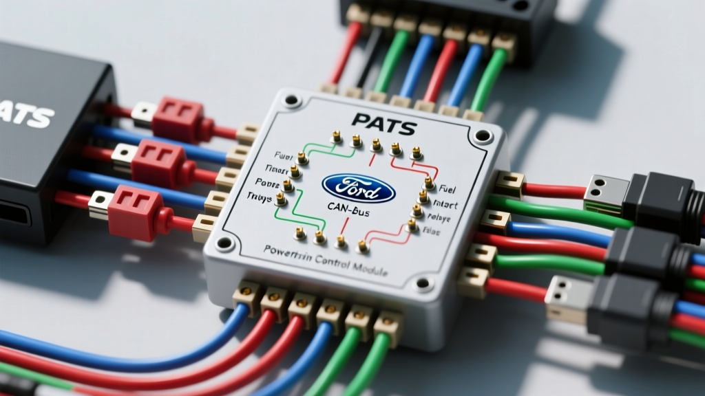
When diagnosing modern no-start conditions, technicians frequently overlook the intricate relationship between the transponder key, the transceiver ring, and the Powertrain Control Module (PCM). The Ford Passive Anti-Theft System (PATS) is a cornerstone of OEM immobilizer technology. Unlike early mechanical steering column locks, PATS relies on a sophisticated digital handshake. Understanding the underlying security system wiring diagram is critical for advanced diagnostics, remote-start bypass integration, and resolving intermittent crank-no-start faults.
At its core, PATS utilizes a 125 kHz Radio Frequency (RF) field to energize a passive glass-capsule transponder embedded in the key head. The transceiver ring, wrapped around the ignition lock cylinder, acts as both an antenna and a modem. It harvests battery voltage, generates the RF field, reads the transponder's unique alphanumeric ID, and translates that data into a digital Pulse-Width Modulated (PWM) signal sent directly to the PCM. If the PCM does not validate this ID within milliseconds of the ignition switch turning to the 'RUN' position, it engages a hardline fuel and starter interrupt.
The Physics of the Transceiver Ring & Inductive Coupling
Before tracing wires, it is vital to understand the physical layer of the security system. The transceiver ring contains a multi-layer copper winding surrounding a ferrite core. When 12V is applied to the transceiver, an internal oscillator circuit drives the coil at precisely 125 kHz. This creates a localized electromagnetic field.
When the PATS key enters this field, the transponder's internal coil resonates, harvesting enough micro-wattage to power its internal ASIC (Application-Specific Integrated Circuit). The transponder then modulates the RF field to transmit its 64-bit ID code back to the transceiver. Because this relies on inductive coupling, physical damage to the transceiver ring—such as micro-fractures in the copper windings or separation from the ferrite core—will alter the resonant frequency, resulting in a 'no-read' condition even if the wiring harness is perfectly intact.
Core Security System Wiring Diagram: Transceiver to PCM
The wiring between the transceiver and the PCM is remarkably minimal but highly sensitive to Electromagnetic Interference (EMI). Below is the definitive pinout and wire gauge specification for the widely used Gen 3 / Gen 4 4-pin transceiver connector (commonly designated as C2007 or C2125 in Ford F-150, Mustang, and Explorer platforms from 2004-2014).
| Pin | Circuit Function | Wire Color | AWG | PCM Cavity (104-Pin) | Signal Type |
|---|---|---|---|---|---|
| 1 | Transceiver Ground (GND) | Black (BK) or Black/Pink | 18 AWG | Pin 25 (SIG RTN) | DC Ground |
| 2 | Transceiver TX (Data to PCM) | White/Red (WH/RD) | 20 AWG | Pin 14 | 5V PWM Square Wave |
| 3 | Transceiver RX (Trigger from PCM) | White/Yellow (WH/YE) | 20 AWG | Pin 15 | 5V Logic Trigger |
| 4 | Voltage Supply (B+ / Ignition) | Red/Yellow (RD/YE) | 18 AWG | N/A (Fuse Panel) | 12V DC |
Critical Wiring Notes & Harness Routing
The TX and RX lines (20 AWG) carry low-voltage, high-frequency digital data. Ford engineering protocols dictate that these wires must be routed away from high-current inductive loads. A common failure mode occurs when aftermarket accessories (like LED headlight drivers or high-amperage winch solenoids) are routed parallel to the steering column harness, inducing voltage spikes that corrupt the PWM handshake. For deep-dive electrical diagnostics and proper oscilloscope probing techniques on these sensitive circuits, reference the foundational guides provided by Haynes Electrical Tutorials.
PCM Logic Gates: Fuel Injector vs. Starter Interrupts
A common misconception is that PATS physically disables the starter motor circuit via a dedicated security relay. While some early iterations and specific commercial fleet vehicles utilized a hardwired starter interrupt relay, the vast majority of consumer Ford PATS implementations rely on PCM logic gates.
- Fuel Injector Ground Control: The PCM controls the fuel injectors by switching the ground path. If the PATS ID is invalid, the PCM's internal logic gate simply refuses to close the ground circuit for the injector drivers. The engine will crank indefinitely but will never fire.
- Starter Relay Inhibit: In later Gen 4 and CAN-bus integrated systems, the PCM communicates over the Medium Speed CAN (MS-CAN) or High Speed CAN (HS-CAN) network to the Smart Junction Box (SJB) or Body Control Module (BCM). If the security handshake fails, the BCM will not provide the ground path for the starter relay coil, resulting in a 'no-crank' condition.
- Theft Indicator LED: The PCM pulses the instrument cluster theft LED via a dedicated hardwire or CAN message. A rapidly flashing LED upon key insertion indicates a transponder read failure or a wiring fault on the TX/RX lines.
Advanced Diagnostics: Oscilloscope Waveform Analysis
Using a Digital Multimeter (DMM) to diagnose PATS data lines is largely ineffective due to the rapid switching of the PWM signals. An automotive oscilloscope is mandatory for verifying signal integrity at the transceiver connector.
Expected Waveform Signatures
- Ignition OFF: Both TX and RX lines should rest at 0V (or a floating 1-2V depending on PCM pull-up resistors).
- Ignition ON (Key Inserted): The PCM sends a 5V logic wake-up pulse on the RX line. Within 50 milliseconds, the transceiver responds on the TX line with a 0-5V square wave. The duty cycle and pulse width of this square wave encode the transponder's binary ID.
- Signal Degradation: If the oscilloscope reveals 'ringing' (overshoot and undershoot on the square wave edges) or a collapsed peak voltage (e.g., 3.2V instead of 5V), you have a high-resistance fault. This is typically caused by terminal fretting corrosion at the 104-pin PCM connector or a compromised splice in the engine bay harness.
Aftermarket Bypass Integration Protocols
Integrating remote starters or push-to-start systems requires bypassing the PATS immobilizer without physically cutting the TX/RX lines or hiding a valet key inside the steering column. Modern bypass modules (such as those from Fortin or iDatalink) utilize a digital interface that connects directly to the vehicle's OBD2 port or the CAN-bus network at the BCM.
Instead of emulating the analog 125 kHz RF field, these modules intercept the HS-CAN / MS-CAN security requests. When the remote start is triggered, the bypass module injects a cryptographically valid security token directly onto the CAN-bus, satisfying the PCM's logic gate. For exact firmware flashing procedures and vehicle-specific CAN-bus wiring topologies, technicians should consult the iDatalink Maestro Technical Support Database. Attempting to hardwire a relay-based bypass on a Gen 4 CAN-bus PATS system will result in permanent BCM bricking and network-wide U-code faults.
Real-World Failure Modes & Repair Strategies
When the security system wiring diagram checks out perfectly, but the vehicle still exhibits a flashing theft light and a no-start condition, consider these advanced failure modes:
- Transceiver Ring Micro-Fractures: The plastic housing of the transceiver ring becomes brittle due to engine bay heat cycling. A microscopic break in the internal copper winding will not show up as an open circuit on a standard DMM continuity test. You must measure the inductance (in millihenries) or substitute a known-good ring.
- PCM 5V Reference Voltage Collapse: The PCM generates the 5V reference for the TX/RX lines. If a separate 5V sensor (like the TPS or MAP sensor) shorts to ground, it can pull down the entire 5V reference bus inside the PCM, killing the PATS transceiver communication. Always check the 5V VREF pin at the PCM if PATS data lines show 0V activity.
- Ignition Coil EMI Bleed: Coil-on-Plug (COP) ignition systems generate massive electromagnetic spikes. If the COP ground strap is corroded, the EMI will seek the path of least resistance, often bleeding into the adjacent PATS transceiver harness. Ensure all engine block and cylinder head ground straps are torqued to spec and free of dielectric grease contamination.
Mastering the PATS architecture requires moving beyond basic continuity testing and embracing digital waveform analysis and network topology. By understanding the precise interaction between the 125 kHz transponder field, the 20 AWG data lines, and the PCM's internal logic gates, technicians can accurately diagnose and resolve the most stubborn immobilizer faults.