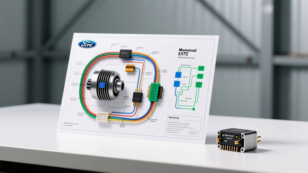
The HVAC Speed Control Dilemma: Manual vs. EATC
When diagnosing a blower motor that only works on high speed, or one that refuses to change speeds in an automatic climate system, technicians often search for a universal Ford blower motor resistor wiring diagram. However, treating all Ford HVAC speed controllers as identical is a critical mistake. Ford utilizes two fundamentally different technologies across its F-150, Explorer, and Focus lineups: the traditional thermal resistor block for Manual A/C, and the solid-state Pulse Width Modulation (PWM) speed controller for Electronic Automatic Temperature Control (EATC). Selecting the incorrect replacement module or misinterpreting the wiring schematic will result in immediate harness failure, melted connectors, or a dead blower circuit.
This guide compares the two systems, provides exact pinout configurations, and details the wire gauge requirements necessary to properly repair or upgrade your Ford HVAC harness.
Product Selection: Identifying Your Speed Controller
Before pulling the glovebox and extracting the wiring harness, you must identify which system your vehicle employs. The physical connector and the dash controls are the primary indicators.
1. Manual A/C: The Thermal Resistor Block
Vehicles equipped with manual rotary dials or sliding levers use a passive resistor block. This component relies on coiled nichrome wire to step down 12V battery voltage to lower speeds. Because it dissipates excess energy as heat, it is mounted directly in the HVAC air duct to rely on blower airflow for cooling. If the blower motor draws excessive amperage (often due to worn bearings), the thermal fuse integrated into the resistor block will blow, leaving the fan operational only on High (which bypasses the resistor entirely).
- Visual Indicator: 4-pin rectangular connector, usually with a coiled wire pigtail.
- Common Motorcraft Part Numbers: YH1795, YH1823.
- Failure Symptom: Blower only works on speed setting 4 (High).
2. EATC: The Solid-State PWM Speed Controller
Higher trim levels featuring digital climate control (EATC) do not use a thermal resistor. Instead, they use a MOSFET-based speed controller module. The EATC head unit sends a variable DC voltage signal (typically 0V to 10V) to the module's gate, which then pulse-width modulates the full 12V battery feed to the blower motor. This allows for infinite variable speed control and soft-start ramping.
- Visual Indicator: 4-pin or 5-pin square connector, heavy-gauge wires, aluminum heat sink fin on the module body.
- Common Motorcraft Part Numbers: YH1935, YH2048.
- Failure Symptom: Blower motor runs continuously on high regardless of ignition state, or remains completely dead.
Ford Blower Motor Resistor Wiring Diagram & Pinout Tables
Below are the specific wiring schematics and pinout tables for both systems. Always verify wire colors against your specific model year, as mid-year production changes can alter secondary tracer colors.
Manual HVAC Resistor Pinout (4-Pin Connector)
| Pin | Wire Color | Function | AWG Size |
|---|---|---|---|
| 1 | Brown/White (BN/WH) | Blower Motor Feed (Output) | 14 AWG |
| 2 | Yellow/Light Green (YE/LG) | Medium-High Speed Input | 16 AWG |
| 3 | White/Blue (WH/BU) | Medium-Low Speed Input | 16 AWG |
| 4 | Black (BK) | Ground / Thermal Fuse Path | 14 AWG |
Schematic Flow: Battery voltage enters the HVAC selector switch. Depending on the dial position, power is routed through Pins 2, 3, or 4 into the nichrome coils. The current exits through Pin 1 to the blower motor. High speed completely bypasses this connector via a dedicated high-speed relay.
EATC Speed Controller Pinout (4-Pin Connector)
| Pin | Wire Color | Function | AWG Size |
|---|---|---|---|
| 1 | Light Blue/Black (LB/BK) | High Current 12V+ Feed | 10 AWG |
| 2 | Black (BK) | Chassis Ground | 12 AWG |
| 3 | Yellow/Red (YE/RD) | EATC PWM Signal Input | 18 AWG |
| 4 | Brown/White (BN/WH) | PWM Output to Blower | 10 AWG |
Schematic Flow: Pin 1 receives constant or ignition-switched 12V+ via a high-amperage fuse (usually 30A or 40A). Pin 3 receives the low-current logic signal from the EATC dash unit. The internal MOSFET chops the 12V+ feed and sends it out of Pin 4 to the blower motor. Pin 2 completes the control circuit ground.
Wire Gauge, Routing, and Connector Selection
One of the most prevalent issues documented in Haynes Ford F-150 Repair Manuals is the melting of the blower motor resistor pigtail. This is rarely a defect in the resistor itself; rather, it is a symptom of voltage drop and high resistance caused by terminal corrosion or an aging blower motor drawing 25+ amps.
Harness Upgrade Specifications
When replacing the speed controller, never reuse the old, heat-cycled connector. You must splice in a new pigtail. For Ford applications, the Motorcraft WPT-1246 (or equivalent OEM harness kit) is highly recommended due to its high-temperature nylon housing and copper-alloy terminals.
- Splicing Method: Do not use twist-lock connectors or standard electrical tape. Use adhesive-lined marine-grade heat shrink crimps.
- Wire Gauge Upgrades: If your vehicle originally utilized 14 AWG for the main blower feed (Pin 1 on Manual, Pins 1 and 4 on EATC), upgrading to SAE J1128 compliant 12 AWG stranded copper wire will significantly reduce voltage drop and heat generation at the terminal interface.
- Dielectric Grease: Apply a ceramic-based dielectric tune-up grease to the terminals before mating the connector to prevent moisture ingress and galvanic corrosion.
Troubleshooting Decision Tree
Use this diagnostic sequence before purchasing a replacement module:
- Verify Blower Motor Amp Draw: Disconnect the blower motor and test it on a bench with a fully charged 12V battery and an inline ammeter. A healthy Ford blower motor should draw between 12 and 16 amps. If it draws over 18 amps, the motor bearings are failing and must be replaced alongside the resistor, or the new resistor will melt within weeks.
- Test the EATC Signal (Auto HVAC only): Backprobe Pin 3 on the EATC speed controller connector with a digital multimeter. With the ignition on and fan speed set to maximum, you should read approximately 10V DC. At minimum speed, you should read 1V to 2V DC. If the signal wire shows 0V, the fault lies in the EATC dash head unit or a broken wire in the dash harness, not the blower module.
- Check the High-Speed Relay: If the fan works on speeds 1 through 3 but dies on High, the resistor block is actually fine. The issue is a failed high-speed blower relay located in the under-hood Battery Junction Box (BJB).
Summary
Interpreting a Ford blower motor resistor wiring diagram requires first confirming whether your vehicle utilizes a manual thermal block or an EATC solid-state controller. By matching the correct Motorcraft component, upgrading degraded wiring harnesses to proper AWG specifications, and verifying the blower motor's baseline amperage draw, you can ensure a permanent repair to your vehicle's HVAC system.