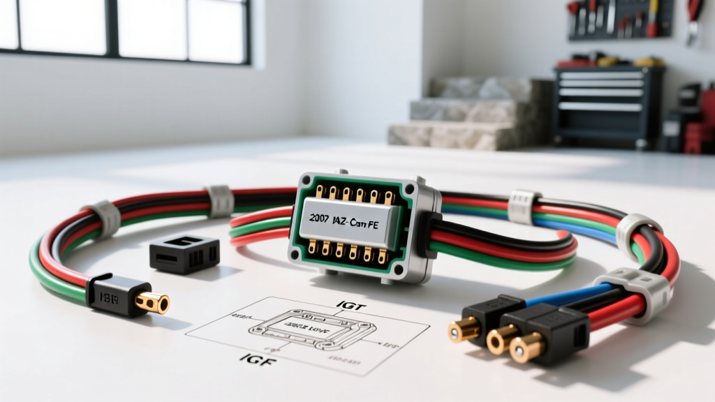
Understanding the 2007 Camry Ignition System Architecture
The 2007 Toyota Camry (XV40 generation) represents a benchmark in mid-size sedan reliability, but its engine management system requires precise electrical integrity to function. Whether your vehicle is equipped with the ubiquitous 2.4L 2AZ-FE inline-4 or the powerful 3.5L 2GR-FE V6, both engines utilize a Coil-on-Plug (COP) ignition system. Unlike older distributor or wasted-spark setups, the COP system places an individual ignition coil directly over each spark plug, eliminating high-voltage spark plug wires and reducing electromagnetic interference (EMI).
To properly diagnose misfires, no-start conditions, or persistent Check Engine Lights (such as P0351 through P0356), a mechanic must move beyond simply swapping parts. Understanding the complete 2007 Toyota Camry ignition coil wiring diagram is critical. This walkthrough dissects the 4-pin COP connector, traces the circuits back to the Engine Control Module (ECM), and provides actionable diagnostic steps using industry-standard testing procedures.
2AZ-FE Ignition Coil Connector Pinout & Wire Specifications
The 2.4L 2AZ-FE engine uses a standardized 4-pin connector for each of its four ignition coils. The pinout is identical across all four cylinders, with the ECM using individual trigger wires for each coil but a shared feedback circuit. Below is the definitive pinout and wire specification chart for the 2AZ-FE COP harness.
| Pin Number | Circuit Function | Wire Color Code | Wire Gauge (AWG) | Destination / Source |
|---|---|---|---|---|
| Pin 1 | IGF (Ignition Feedback) | Yellow (Y) | 20 AWG | ECM Connector E5 (Pin 12) |
| Pin 2 | IGT (Ignition Trigger) | White/Black (W-B) | 20 AWG | ECM Connector E4 (Pins 21-24) |
| Pin 3 | Ground (E1) | Brown (BR) | 16 AWG | Engine Block Ground / ECM |
| Pin 4 | Power (+B) | Black/White (B-W) | 14 AWG | EFI Relay (Integration Fuse) |
Note: The 3.5L 2GR-FE V6 utilizes a nearly identical 4-pin logic structure, but wire colors vary slightly (e.g., IGT wires are often White/Red or White/Green depending on the specific harness batch), and the rear bank coils are buried beneath the upper intake plenum, requiring plenum removal for physical access.
Complete Circuit Walkthrough: Tracing the Signals
To effectively use the 2007 Toyota Camry ignition coil wiring diagram, you must understand the purpose of each of the four wires. A COP coil is essentially a transformer with an internal power transistor (igniter). Here is how the ECM manages the spark event.
1. The +B Power Circuit (Pin 4)
Power is supplied to Pin 4 via the EFI (Electronic Fuel Injection) relay. When the ignition key is turned to the 'ON' position, the ECM grounds the EFI relay coil, closing the contacts and sending battery voltage (12V+) through a 15A or 20A fuse to a splice pack in the engine harness. From the splice pack, 14 AWG Black/White wires branch out to each coil. If you have a dead coil with no power, the issue is rarely the individual wire; it is almost always a blown EFI fuse, a faulty EFI relay, or corrosion at the main harness splice pack located near the strut tower.
2. The Ground Circuit (Pin 3)
Pin 3 provides the necessary ground path for the coil's internal primary windings and logic board. This 16 AWG Brown wire routes to a primary engine ground point on the cylinder head or block, which ultimately ties back to the battery negative terminal and the ECM ground reference. A poor ground here will result in a weak spark, causing a random misfire (P0300) or specific cylinder misfire codes, often accompanied by a noticeable voltage drop across the coil casing.
3. The IGT Trigger Signal (Pin 2)
The Ignition Trigger (IGT) is the command signal sent from the ECM to the coil. The ECM pulls this 5V logic signal to ground (0V) to tell the coil's internal igniter to close the primary circuit, building a magnetic field. When the ECM releases the signal back to 5V, the primary field collapses, inducing the high-voltage spark in the secondary winding. Each cylinder has a dedicated IGT wire (e.g., IGT1 for Cylinder 1, IGT2 for Cylinder 2) to allow the ECM to control spark timing and dwell individually.
4. The IGF Feedback Signal (Pin 1)
The Ignition Feedback (IGF) is a critical failsafe circuit. After the coil fires, it sends a low-voltage pulse back to the ECM on the Yellow wire. This confirms to the ECM that a spark event actually occurred. Crucial Diagnostic Insight: If the ECM does not receive an IGF signal for 5 to 6 consecutive ignition cycles, it assumes the coil has failed and will intentionally shut off the fuel injectors for that cylinder. This prevents raw, unburnt fuel from entering the exhaust and destroying the catalytic converter. Therefore, a dead coil will often result in a fuel injector circuit code alongside the ignition code.
Step-by-Step Diagnostic Testing Procedures
When diagnosing a misfire on the 2007 Camry, avoid the 'parts cannon' approach. Follow this structured diagnostic tree using a high-impedance Digital Volt-Ohm Meter (DVOM) and an automotive logic probe.
Step 1: Verify Power and Ground (Static Test)
- Disconnect the ignition coil connector.
- Turn the ignition to the 'ON' position (engine off).
- Using your DVOM, probe the harness-side Pin 4 (+B). You should read battery voltage (12.2V - 12.6V). If 0V, check the EFI fuse and relay.
- Probe harness-side Pin 3 (Ground) using the resistance (Ohms) setting. Measure between Pin 3 and the negative battery terminal. Resistance should be less than 0.5 ohms. If higher, locate and clean the engine block ground strap.
Step 2: Verify IGT Trigger Signal (Dynamic Test)
WARNING: Never use a standard incandescent test light on the IGT or IGF circuits. The test light will draw excessive current and permanently fry the internal driver transistor inside the ECM. Use a high-impedance logic probe or an oscilloscope.
- Reconnect the coil harness and use a back-probe pin on the IGT wire (Pin 2).
- Connect your logic probe or oscilloscope to the back-probe.
- Crank the engine. The logic probe should pulse between 0V and 5V. On an oscilloscope, you will see a clean square wave dropping to near 0V during the dwell phase, then spiking to 5V+ when the spark fires.
- If the signal is missing on one cylinder but present on others, trace the specific White/Black wire back to the ECM E4 connector for an open circuit or chafed insulation.
Step 3: Verify IGF Feedback Signal
- Back-probe the IGF wire (Pin 1, Yellow).
- Crank the engine. You should see a pulsing 0V to 5V square wave that is slightly offset from the IGT signal (the IGF pulse occurs exactly when the IGT signal is released).
- If IGT is present but IGF is absent, the internal igniter in the ignition coil has failed. Replace the coil assembly.
Common Wiring Failure Modes on the 2007 Camry
Based on extensive field diagnostics and Toyota Technical Information System (TIS) service bulletins, the XV40 Camry experiences a few recurring electrical faults related to the ignition harness:
- Valve Cover Heat Degradation: The 2AZ-FE engine runs hot at the coil boots. Over time, the heat causes the PVC insulation on the 20 AWG IGT and IGF wires to become brittle and crack. This leads to short-to-ground misfires that only occur when the engine reaches operating temperature and the harness softens.
- 2GR-FE V6 Plenum Chafing: On the V6 model, the rear bank ignition harness is routed tightly against the aluminum bracket of the upper intake plenum. Engine torque movement causes the harness loom to wear through, resulting in the IGT wires shorting against the grounded intake manifold. This typically triggers multiple misfire codes (e.g., P0304, P0305, P0306) simultaneously.
- Connector Pin Fretting: The 4-pin connectors are prone to moisture intrusion if the secondary spark plug tube seals leak oil into the spark plug wells. Oil acts as an insulator and attracts dust, causing terminal fretting and high resistance on the low-amperage IGF signal line.
Harness Repair Best Practices
If you discover damaged wiring near the coil connectors, do not simply twist wires together and wrap them in electrical tape. Engine bay repairs require adherence to SAE International standards for automotive wiring.
- Wire Selection: Always use Cross-Linked Polyethylene (TXL) or GXL automotive wire. Standard THHN household wire will melt and fail under hood temperatures.
- Splicing: Use adhesive-lined heat shrink butt connectors or open-barrel crimp splices. The adhesive lining melts and seals the connection against oil and moisture intrusion.
- Loom Replacement: After repairing the wires, wrap the harness in high-temperature Tesa tape or corrugated nylon loom to protect against abrasion and radiant heat from the exhaust manifold.
Authoritative References
For further technical data, wiring schematics, and ECM pinout matrices, consult the following resources:
- Toyota Technical Information System (TIS) - Official OEM service manuals and wiring diagrams for the XV40 Camry.
- SAE International J2534 - Standards for automotive electrical diagnostics and pass-thru programming.
- Haynes Toyota Camry Repair Manual - Comprehensive aftermarket wiring guides and torque specifications for engine harness routing.