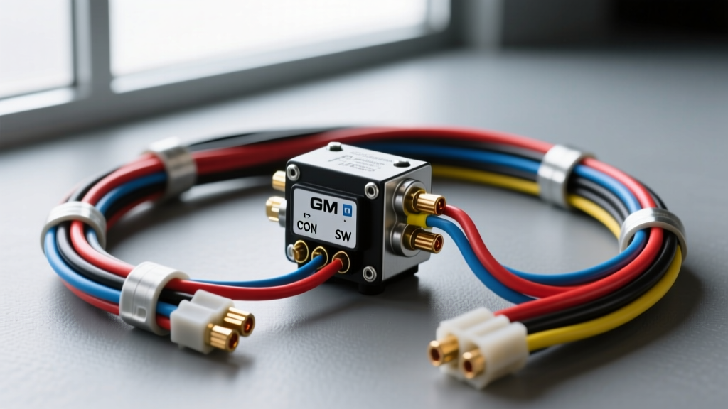
Why Factory Air Conditioner Diagram Wiring Fails on Classic Trucks
When retrofitting or restoring the A/C system on a 1973-1987 GM C10 (Squarebody), relying on the original factory air conditioner diagram wiring is a recipe for electrical failure. The OEM circuit was designed to carry the full amperage draw of the original Harrison A6 compressor clutch directly through the dashboard HVAC rotary switch and the low-pressure cycling switch. Over four decades, the copper strands inside the OEM Dark Green (CKT 59) and Light Blue (CKT 60) wires degrade, and the switch contacts develop high resistance.
If you are upgrading to a modern Sanden SD7H15 R-134a compressor, the clutch coil demands a solid 12V supply to engage reliably. A voltage drop of even 1.5 volts across the aging factory harness will result in severe 'clutch chatter,' rapid cycling, and eventual burnout of the clutch coil. To solve this, we must bypass the high-amp load from the factory switches by integrating a modern 30A Bosch-style ISO relay. This guide provides a comprehensive, practical approach to upgrading your air conditioner diagram wiring for bulletproof A/C operation.
Upgraded Air Conditioner Diagram Wiring: Component Overview
Before cutting or splicing any wires, gather the correct automotive-grade materials. Using hardware store wire and electrical tape will lead to under-hood failures due to heat and vibration. You will need:
- Wire: Cross-linked polyethylene (GXL) automotive wire. 10 AWG (Red) for main power, 12 AWG (Dark Green) for clutch feed, and 16 AWG (Black/Light Blue) for trigger and ground circuits.
- Relay: Standard 12V 30A Bosch-style ISO Mini Relay (5-pin).
- Connectors: Weather-Pack 2-pin (150 series) for the Sanden compressor clutch, and sealed Metri-Pack 280 terminals for the relay.
- Safety Switch: R-134a Binary Safety Switch (Vintage Air or Four Seasons) to monitor both high and low-side pressures.
- Protection: 30A Maxi-Fuse, Adel P-clamps, and adhesive-lined heat shrink tubing.
Table: Bosch-Style ISO Mini Relay Pinout Specifications
| Pin Number | Terminal Type | Function in A/C Circuit | Recommended AWG |
|---|---|---|---|
| 30 | Common (Input) | Fused 12V+ direct from battery | 10 AWG (Red) |
| 87 | Normally Open (Output) | 12V+ feed to compressor clutch coil | 12 AWG (Dark Green) |
| 86 | Coil (+) | 12V+ trigger from OEM HVAC dash switch | 16 AWG (Light Blue) |
| 85 | Coil (-) | Ground path routed through Binary Switch | 16 AWG (Black) |
| 87a | Normally Closed | Not used (tape off and seal) | N/A |
Step-by-Step Compressor Clutch Wiring Installation
Step 1: Establishing the High-Amp Power Feed
Begin at the battery positive terminal. Install a 30A Maxi-Fuse within 6 inches of the battery post to protect the circuit in case of a dead short. Run a length of 10 AWG GXL Red wire from the fuse block to Pin 30 on the Bosch relay. Route this wire along the inner fender, securing it every 8 inches with Adel P-clamps to keep it away from the exhaust manifolds. Terminate the wire at the relay using a crimped and sealed Metri-Pack 280 female terminal. Expert Tip: Never solder under-hood automotive connections; solder wicks up the wire strand, creating a rigid point that will snap under engine vibration. Always use a proper ratcheting crimp tool.
Step 2: Wiring the Binary Safety Switch
The binary switch is non-directional and simply acts as a gatekeeper for the ground circuit. Mount the binary switch on the R-134a high-side line or accumulator using a Schrader valve adapter. Run a 16 AWG Black wire from Relay Pin 85 to one terminal of the binary switch. Run a second 16 AWG Black wire from the other terminal of the binary switch to a clean, bare-metal ground on the engine block or firewall. Torque the ground eyelet to 15 lb-ft and coat the connection with dielectric grease to prevent galvanic corrosion.
Step 3: Triggering the Relay via the OEM HVAC Switch
Locate the factory A/C clutch wire near the HVAC control head or the factory low-pressure switch on the accumulator. On 1973-1987 GM C10s, this trigger wire is typically Dark Green or Light Blue. Using a T-tap or, preferably, by cutting the wire and using a sealed butt-splice, connect this OEM low-amp trigger wire to Relay Pin 86 using a 16 AWG Light Blue wire. When you turn the dash slider to 'A/C', the factory switch sends a low-current 12V+ signal to Pin 86, energizing the relay coil without stressing the 40-year-old dash contacts.
Step 4: The Clutch Feed and Flyback Diode
Run a 12 AWG Dark Green wire from Relay Pin 87 down to the Sanden compressor clutch. Terminate this end with a Weather-Pack 2-pin connector. Critical Addition: The compressor clutch is an electromagnetic coil. When the relay opens, the collapsing magnetic field generates a high-voltage spike (flyback voltage) that can arc across the relay contacts and fry sensitive vehicle electronics. To prevent this, solder a 1N4001 rectifier diode across Relay Pins 85 and 86. The diode's silver band (cathode) must point toward Pin 86 (the 12V+ trigger side). This safely recirculates the voltage spike back into the coil.
R-134a Binary Switch Pressure Specifications
Understanding the thresholds of your binary switch is crucial for diagnosing why a clutch may not engage. According to Four Seasons Automotive Technical Resources, modern R-134a binary switches are calibrated to protect the compressor from liquid slugging (low pressure) and catastrophic hose rupture (high pressure).
Table: Standard R-134a Binary Switch Thresholds
| Function | Pressure Threshold (PSI) | Electrical State | System Protection Goal |
|---|---|---|---|
| Low-Pressure Cut-Out | Opens at 25 PSI | Circuit Broken (Clutch Off) | Prevents compressor operation without refrigerant/oil |
| Low-Pressure Cut-In | Closes at 45 PSI | Circuit Complete (Clutch On) | Ensures adequate evaporator pressure to prevent freezing |
| High-Pressure Cut-Out | Opens at 406 PSI | Circuit Broken (Clutch Off) | Prevents hose rupture and compressor over-pressurization |
| High-Pressure Cut-In | Closes at 340 PSI | Circuit Complete (Clutch On) | Resumes operation once condenser sheds excess heat |
Troubleshooting the Air Conditioner Diagram Wiring
Even with a flawless installation, A/C electrical gremlins can occur. Use this symptom-cause-fix decision tree to diagnose issues rapidly, referencing Haynes GM Full-Size Trucks Repair Manuals for baseline factory testing procedures.
Symptom-Cause-Fix Decision Tree
- Symptom: Compressor clutch cycles on and off rapidly (every 1-2 seconds).
- Cause: Low refrigerant charge causing the binary switch to hit the 25 PSI cut-out, or an evaporator freeze-up due to a faulty thermostatic expansion valve (TXV).
- Fix: Connect manifold gauges. If low-side pressure drops below 25 PSI while running, add R-134a. If pressures are normal, check the evaporator core for ice buildup.
- Symptom: Clutch engages but slips or squeals under high RPM.
- Cause: Voltage drop at the clutch coil. The coil is receiving less than 11.5V, resulting in a weak magnetic field.
- Fix: Perform a voltage drop test across the clutch connector while the engine is running. If voltage is below 12.0V, check the ground eyelet for corrosion or verify the 10 AWG power feed to Pin 30 is secure.
- Symptom: Clutch will not engage, but dash switch has 12V output.
- Cause: Open circuit in the binary switch ground path, or a blown 30A Maxi-Fuse.
- Fix: Bypass the binary switch temporarily with a jumper wire. If the clutch engages, the system is either completely out of refrigerant or the binary switch is internally failed. Check the SAE J2064 hose specifications for proper R-134a barrier hose usage to prevent micro-leaks.
Final Routing and Verification
Once all connections are crimped, heat-shrunk, and tested, zip-tie the wiring harness securely to the engine wiring loom. Ensure the Dark Green clutch feed wire has a generous drip loop before entering the Weather-Pack connector at the compressor; this prevents water from wicking down the wire and into the coil cavity. By upgrading your air conditioner diagram wiring with a dedicated relay and binary safety switch, you eliminate the weak points of the factory GM C10 design, ensuring your Sanden compressor receives the clean, high-amperage 12V power it requires for years of ice-cold performance.
Sources:
1. Haynes GM Full-Size Trucks 1980-1987 Repair Manual
2. SAE J2064: R-134a Refrigerant Hose Specifications
3. Four Seasons Automotive Technical Resources & Retrofit Guides