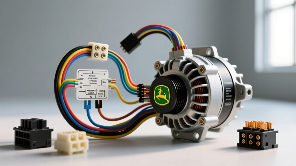
Understanding Your John Deere Charging System
Whether you are restoring a classic John Deere 4020, maintaining a modern 1025R sub-compact, or performing a custom 12-volt conversion on a vintage two-cylinder model, understanding your charging system is critical. The alternator is the heart of your tractor's electrical system, responsible for powering accessories, lighting, and ECU modules while keeping the battery fully charged. For beginners, staring at a John Deere alternator wiring diagram can feel overwhelming due to the mix of OEM harness colors, aftermarket modifications, and varying alternator styles.
This guide breaks down the fundamentals of alternator wiring, focusing on the most common setups found in the John Deere ecosystem. We will cover the visual layout of standard wiring schematics, the critical differences between 1-wire and 3-wire configurations, and provide actionable, step-by-step instructions to ensure your tractor charges reliably under heavy agricultural loads.
1-Wire vs. 3-Wire Alternator Configurations
Before cutting, crimping, or routing any wire, you must identify which type of alternator you are working with. John Deere tractors utilize both styles depending on the era and whether the unit is factory-original or an aftermarket upgrade.
The 3-Wire Setup (Factory Standard)
Most factory-equipped John Deere tractors from the 1970s through the early 2000s use a 3-wire alternator (commonly the Delco 10SI, 12SI, or Hitachi/Nippondenso equivalents). A 3-wire diagram includes:
- BAT Terminal: The main power output connected directly to the battery positive terminal or starter solenoid.
- Terminal 1 (Sense): Reads the actual voltage at the battery or fuse block to tell the internal voltage regulator how much charge to produce.
- Terminal 2 (Exciter): Receives a 12V signal from the ignition switch or dashboard warning lamp to 'wake up' the alternator and begin charging.
The 1-Wire Setup (Aftermarket Conversion)
Many beginners opt for a '1-wire' alternator when replacing a failed factory unit or converting a 6-volt JD tractor to 12 volts. A 1-wire alternator has an internal self-exciting voltage regulator. It requires only a single heavy-gauge wire from the BAT terminal to the battery. While easier to wire, 1-wire alternators often require the engine to be revved to 1,200+ RPM to 'turn on' and may struggle to maintain voltage at low idle speeds when running high-draw accessories like halogen work lights or electric PTO clutches.
The Standard John Deere Alternator Wiring Diagram
Visualize a standard 3-wire John Deere alternator diagram as a triangle connecting the alternator, the ignition switch, and the battery. Below is the technical breakdown of the most common alternator found on classic and mid-range JD tractors: the Delco 10SI and 12SI series.
Delco 10SI & 12SI Pinout and Wire Gauge Specifications
When building or repairing your harness, adhering to SAE J1128 wire standards is crucial to prevent voltage drop and potential electrical fires. Use the following specification chart to build your harness:
| Terminal / Pin | Function | Typical JD / OEM Wire Color | Recommended AWG Size | Connection Point & Notes |
|---|---|---|---|---|
| BAT Post | Main DC Output | Red | 10 AWG (or 8 AWG for runs over 4 ft) | Battery Positive (+) or Starter Solenoid. Must include a 60A-100A inline Maxi-Fuse or fusible link. |
| Terminal #1 (Sense) | Voltage Sense | Yellow or Red/White | 16 AWG | Ignition side of the ballast resistor or directly to the battery (+) for the most accurate voltage regulation. |
| Terminal #2 (Exciter) | Field Excitation | Brown or White | 16 AWG | Dashboard 'ALT' warning lamp, then to the Ignition Switch 'ON' terminal. Requires a 10-ohm resistor if no dash lamp is used. |
| Case Ground | Circuit Completion | N/A (Bare Metal) | 10 AWG (Dedicated Strap) | Alternator case to engine block. Critical if mounting brackets are painted or powder-coated. |
Step-by-Step Wiring Guide for Beginners
Follow these steps to wire a 3-wire alternator on your John Deere tractor safely and effectively.
Step 1: Prepare the Main BAT Wire
Cut a length of 10 AWG red SAE GXL wire. Crimp a 5/16-inch ring terminal on one end for the alternator BAT post and a 3/8-inch ring terminal for the battery or starter solenoid. Pro Tip: Always use adhesive-lined heat shrink tubing over your crimps. John Deere tractors operate in high-vibration, high-dust environments; standard vinyl electrical tape will peel and fail, leading to corrosion.
Step 2: Wire the Exciter Circuit (Terminal 2)
Using 16 AWG wire, connect Terminal 2 to your ignition switch. If your JD tractor has a dashboard charge indicator light, wire Terminal 2 to the negative side of the bulb. The bulb provides the initial resistance needed to excite the alternator's rotor. If you are bypassing the dash light, you must wire a 10-ohm, 2-watt resistor in parallel with the wire to prevent the alternator from failing to turn on.
Step 3: Route the Sense Wire (Terminal 1)
For optimal performance, especially when running heavy hydraulic pumps or electric clutches, run the Terminal 1 sense wire directly to the positive terminal of the battery or the main terminal block. This ensures the voltage regulator reads the true battery state, rather than the voltage at the alternator, compensating for any voltage drop across the tractor's main harness.
Step 4: Establish a Dedicated Ground
Never assume the alternator mounting bracket provides a sufficient ground. Paint, rust, and grease act as insulators. Install a dedicated 10 AWG ground strap from the alternator case to a clean, bare-metal spot on the engine block or cylinder head.
Upgrading Vintage JD Tractors: Generator to Alternator
Many beginners purchase vintage letter-series John Deere tractors (e.g., Model A, B, or 40) that originally came with 6-volt DC generators. Upgrading to a 12-volt 1-wire alternator is one of the most popular and reliable modifications you can perform.
When executing this conversion, you must remove the old voltage regulator and generator. Wire the single 10 AWG output wire from the new 1-wire alternator directly to the 'BAT' terminal on your starter solenoid. You will also need to replace the old ammeter with a 12-volt voltmeter, or ensure your original ammeter is rated for the higher amperage output of a modern alternator (typically 60A+). Furthermore, ensure you have swapped the ignition coil to a 12-volt variant or retained the original coil with an inline ballast resistor to prevent burning out the points.
Troubleshooting Common Charging Failures
Even with a perfect wiring diagram, tractors endure harsh conditions. If your John Deere is not charging, perform a Voltage Drop Test before replacing the alternator. This test, endorsed by experts at Powermaster Performance, identifies hidden resistance in your wiring.
- Start the tractor and turn on the headlights and work lights to place a load on the system.
- Set your digital multimeter to DC Volts.
- Place the red probe on the alternator's BAT post and the black probe on the positive terminal of the battery.
- A reading of 0.0V to 0.2V indicates a healthy wire. A reading above 0.5V means your BAT wire is undersized, corroded, or has a failing crimp.
- Repeat the test on the ground side: Red probe on the alternator case, black probe on the negative battery terminal. High voltage here indicates a poor engine ground strap.
Authoritative References & Further Reading
For deeper dives into OEM harness routing and specific model-year pinouts, consult the following resources:
- SAE International J1128: Standard specifications for automotive primary wire insulation and gauge requirements.
- Powermaster Performance Wiring Tech: Comprehensive guides on alternator excitation, voltage drop testing, and high-amperage routing.
- TractorByNet John Deere Forums: An invaluable community database for model-specific wiring quirks, particularly for 10-series and vintage letter-series conversions.
By understanding the core principles of the John Deere alternator wiring diagram, you can confidently diagnose, repair, and upgrade your tractor's charging system, ensuring it starts reliably and powers your implements for seasons to come.