Introduction to Aftermarket Fog Light Upgrades
When executing a lighting upgrade project on a vehicle that did not come equipped with factory fog lamps, or when upgrading weak OEM halogen units to high-output LEDs, managing electrical current safely is paramount. Relying on the factory headlight switch or a simple dashboard toggle to carry the full amperage of auxiliary lamps is a recipe for melted switch housings, voltage drop, and potential electrical fires. This is why utilizing a dedicated wiring diagram for fog lights with relay integration is the gold standard for automotive electrical modifications.
By incorporating a Bosch-style ISO 7588 mini relay into your harness, you separate the high-current load circuit from the low-current trigger circuit. This guide provides an expert-level breakdown of the wiring schematic, wire gauge requirements, terminal crimping standards, and modern CAN-bus considerations necessary for a flawless, OEM-grade fog light installation.
The Physics and Logic of Relay Integration
A standard automotive relay acts as an electrically operated switch. In a fog light modification, the relay allows a low-amperage switch (typically 2A to 5A) to control a high-amperage circuit (10A to 20A) that directly powers the lamps. This minimizes the length of the high-current wire run and ensures that the dashboard switch only handles the minimal current required to energize the relay's internal electromagnetic coil.
Furthermore, routing the primary 12V+ power directly from the battery (or main distribution stud) through a dedicated fuse ensures that the fog lights receive maximum voltage. Voltage drop across long, undersized wires or factory headlight circuits can severely reduce the lumen output of halogen bulbs and cause LED drivers to flicker or shut down due to low-voltage protection thresholds.
Standard ISO Mini Relay Pinout Diagram
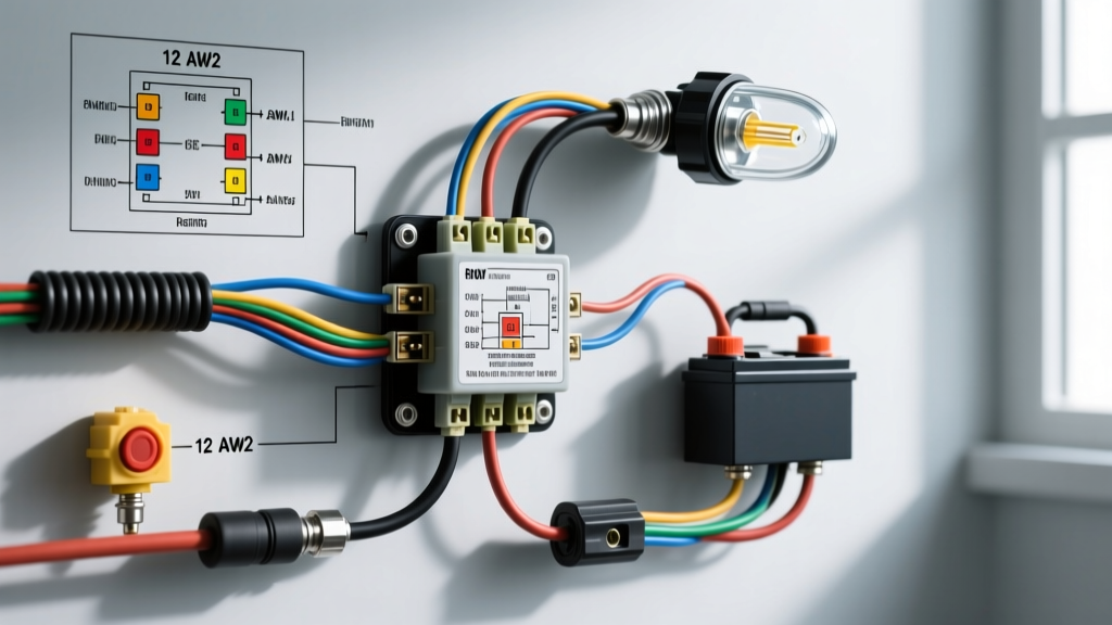
The most common relay used in automotive lighting upgrades is the ISO 7588-1 Mini Relay (often referred to as a Bosch-style relay). Understanding the terminal numbering is critical before cutting or crimping any wire.
| Pin Number | Function | Wire Color (Typical) | AWG Size | Connection Destination |
|---|---|---|---|---|
| 30 | Common / Power Input | Red | 12 AWG TXL | Battery Positive (+) via Inline Fuse |
| 87 | Normally Open (NO) Output | Red or Blue | 12 AWG TXL | Fog Light Positive (+) Terminals |
| 85 | Coil Ground | Black | 16 AWG TXL | Chassis Ground or Battery Negative (-) |
| 86 | Coil Trigger / Switch Input | White or Yellow | 16 AWG TXL | Dashboard Toggle Switch Output |
Note: On standard ISO mini relays without an internal suppression diode or resistor, pins 85 and 86 are interchangeable. However, if your relay includes an internal diode (marked by a small triangle symbol on the relay casing), polarity matters: Pin 86 must be the positive trigger, and Pin 85 must be ground.
Step-by-Step Upgrade Modification Guide
Phase 1: Power and Ground Routing (The Load Circuit)
Begin by measuring and cutting 12 AWG TXL (Thin-wall cross-linked) wire for the main power and ground runs. TXL wire is specified by the SAE J1128 Standard for its high-temperature resistance and thin insulation profile, making it ideal for routing through tight engine bays.
- Battery Connection: Crimp a 12-10 AWG closed-end ring terminal onto the red 12 AWG wire. Use a hex-crimp tool (not a simple indent crimp) to ensure a gas-tight connection. Slide the wire into an inline ATO/ATC waterproof fuse holder, positioned within 8 inches of the battery positive terminal.
- Relay Connection: Route the wire to the relay location (ideally mounted on the fender well or radiator support, away from exhaust heat). Crimp a 1/4-inch (6.3mm) female quick-disconnect terminal to the wire and plug it into Pin 30.
- Load Output: Connect a 12 AWG wire from Pin 87 to the positive pins of your fog light connectors. For H11 or H3 bulbs, use OEM-style Weather-Pack or Deutsch DT connectors to ensure a waterproof seal.
- Grounding: The fog lights must be grounded to the chassis. Locate a bare metal bolt on the subframe or radiator support. Remove any paint or powder coating, attach a 12 AWG ring terminal using a star washer to bite into the metal, and coat the connection in dielectric grease to prevent galvanic corrosion.
Phase 2: Switch Trigger Circuit (The Control Circuit)
The trigger circuit requires significantly less current, allowing the use of 16 AWG wire.
- Switch Power: Run a 16 AWG wire from an ignition-switched 12V source (such as the radio fuse or wiper fuse) using an Add-A-Circuit (fuse tap). Do not splice directly into factory headlight wires on modern vehicles (see CAN-bus section below).
- Switch to Relay: Connect the output of your dashboard toggle switch to Pin 86 on the relay.
- Relay Ground: Connect Pin 85 to a clean, unpainted chassis ground using a 16 AWG wire and a #10 ring terminal.
Modern Vehicle CAN-Bus and PWM Considerations
If you are performing this upgrade on a modern vehicle (typically 2010 and newer, including Ram, Ford, and GM platforms), the Body Control Module (BCM) actively monitors the headlight circuits for voltage drops to detect blown bulbs. Furthermore, many modern vehicles use Pulse Width Modulation (PWM) to control headlight brightness and daytime running lights (DRLs), meaning the voltage at the headlight plug is not a steady 12V, but a rapidly pulsing signal.
If you wire your relay trigger (Pin 86) directly to an OEM headlight wire on a PWM system, the relay will chatter violently, overheat, and fail within minutes. Additionally, the BCM may register the added current draw of the relay coil as a circuit fault, triggering a 'Bulb Out' warning on the dashboard and cutting power to the circuit entirely.
The Solution: Always use an Add-A-Circuit (Fuse Tap) in the interior fuse box to trigger the fog light relay. Tap into an ignition-switched circuit (like the 12V accessory outlet or heated seats module) to provide a clean, steady 12V+ signal to your dashboard switch, completely bypassing the BCM's headlight monitoring logic.
Wire Gauge, Fuse, and Wattage Matrix
Selecting the correct fuse and wire gauge is dictated by the total wattage of your fog lights. The following chart assumes a standard 12.5V charging system and accounts for a 20% safety margin for inrush current.
| Total Lamp Wattage | Amperage Draw (at 12.5V) | Minimum Wire Gauge (Up to 15ft) | Required ATO/ATC Fuse |
|---|---|---|---|
| 110W (2x 55W Halogen H11) | 8.8A | 14 AWG (12 AWG Recommended) | 15A |
| 200W (2x 100W Off-Road) | 16.0A | 12 AWG | 20A |
| 60W (2x 30W LED Pods) | 4.8A (Plus Inrush) | 16 AWG (14 AWG Recommended) | 10A |
Reference: Fuse sizing and time-current characteristics are based on Littelfuse ATO/ATC Specifications.
Troubleshooting Common Relay Modification Failures
Even with a perfect wiring diagram for fog lights with relay, physical installation errors can cause system failures. Use this diagnostic tree to troubleshoot common issues:
- Symptom: Fog lights do not turn on; relay does not click.
- Cause: No trigger signal reaching Pin 86, or Pin 85 ground is floating.
- Fix: Use a digital multimeter (DMM) to test voltage between Pin 86 and the battery negative terminal while the switch is ON. If 12V is present, check the continuity of Pin 85 to chassis ground. Clean the ground point and ensure the star washer is biting into bare metal.
- Symptom: Relay clicks rapidly (chattering) or lights flicker.
- Cause: Trigger wire is spliced into a PWM-controlled OEM headlight circuit, or the relay ground (Pin 85) is sharing a ground with the high-current load, causing voltage bounce.
- Fix: Reroute the trigger wire to an Add-A-Circuit fuse tap. Ensure Pin 85 is grounded to a dedicated, clean chassis point, separate from the fog light grounds.
- Symptom: Fog lights remain ON after the switch is turned off.
- Cause: The relay is internally welded closed due to arcing from an oversized load (exceeding the 30A/40A relay rating), or a backfeed is occurring through an LED switch indicator light.
- Fix: Replace the relay. If using a dashboard switch with an internal LED indicator, ensure the switch is wired correctly so the indicator draws power from a separate illumination circuit, not backfeeding through the relay coil.
Authoritative References
- SAE J1128: Low Tension Primary Cable Standard - Defines insulation thickness and temperature ratings for automotive TXL/GXL wire.
- Hella Automotive Relay Guide - Comprehensive reference for ISO 7588 mini relay pinouts and load capacities.
- Littelfuse ATO/ATC Datasheet - Blade fuse time-current curves and ampacity ratings for automotive circuit protection.