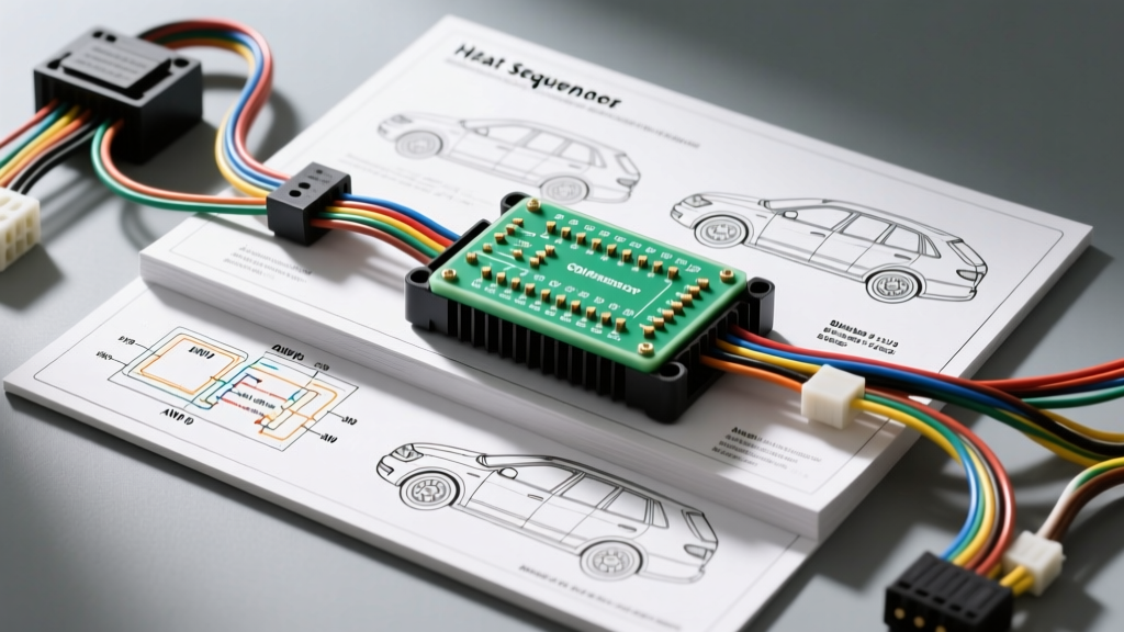
Technical Reference: Automotive Heat Sequencer Wiring Schematics
In modern automotive and heavy-duty applications, managing massive electrical loads during cold-weather operation is critical to prevent alternator failure and voltage brownouts. A heat sequencer module acts as the central brain for staging high-amperage thermal devices—most notably diesel intake air heaters (grid heaters) and Electric Vehicle (EV) Positive Temperature Coefficient (PTC) cabin heaters. This technical specification reference provides the definitive wiring diagram for heat sequencer circuits, detailing OEM pinouts, wire gauges, and control logic.
Core Functionality: Why Sequencing is Critical
When a diesel engine is cranked in sub-freezing temperatures, the intake grid heater can draw between 120A and 180A. If the glow plugs, grid heater, and blower motor engage simultaneously, the combined draw can exceed 250A, instantly overwhelming a standard 140A to 220A alternator and draining the batteries. The heat sequencer prevents this by pulse-width modulating (PWM) or staging the relays based on battery voltage, alternator output, and intake air temperature (IAT). In EV architectures, the PTC heat sequencer manages high-voltage (HV) coolant heaters, ramping up current draw to prevent tripping the battery management system (BMS) overcurrent protection.
Wiring Diagram for Heat Sequencer: Diesel Grid Heater Systems
The following schematic data applies to heavy-duty and light-duty diesel applications (e.g., Cummins ISB 5.9L/6.7L and Ford Powerstroke platforms) utilizing a dual-stage intake air heater contactor setup managed by the Powertrain Control Module (PCM) or a dedicated sequencer relay box.
ECM to Sequencer Control Pinout (6-Pin Deutsch DT Connector)
The low-current control side of the heat sequencer relies on a sealed 6-pin connector. The ECM provides switched grounds or 12V triggers to engage the heavy-duty solenoids.
- Pin 1 (Ignition Feed): 18 AWG, Red/White stripe. Provides 12V reference from the ignition relay.
- Pin 2 (Sensor Ground): 20 AWG, Black. Dedicated analog ground for the IAT sensor.
- Pin 3 (Stage 1 Solenoid Trigger): 14 AWG, Yellow. ECM switched ground. Engages the first 100A grid heater element.
- Pin 4 (Stage 2 Solenoid Trigger): 14 AWG, Green/Black stripe. ECM switched ground. Engages the second element only if system voltage remains above 12.2V.
- Pin 5 (IAT Sensor Signal): 20 AWG, Shielded Grey. 5V reference return from the Intake Air Temperature thermistor.
- Pin 6 (Chassis Ground): 12 AWG, Black. Main module ground, must be ring-terminated to the engine block.
High-Current Power Circuit Specifications
| Circuit Path | AWG Size | Wire Type | Termination | Max Amperage |
|---|---|---|---|---|
| Battery (+) to Sequencer Busbar | 2/0 AWG | Fine-strand welding cable | 3/8" Copper Lug, crimped & sealed | 200A Continuous |
| Sequencer to Grid Heater Element 1 | 1/0 AWG | TXL High-Temp | M8 Ring Terminal, torque to 18 lb-ft | 120A Peak |
| Sequencer to Grid Heater Element 2 | 1/0 AWG | TXL High-Temp | M8 Ring Terminal, torque to 18 lb-ft | 120A Peak |
| Alternator Sense Wire | 16 AWG | Shielded Twisted Pair | ECM Harness Breakout | < 1A |
EV and Hybrid PTC Heat Sequencer Schematics
In electric and hybrid vehicles, cabin heating and battery thermal management rely on High-Voltage (HV) PTC heaters. The heat sequencer in this context is typically integrated into the Thermal Management Control Module (TMCM). Unlike the simple on/off solenoids of a diesel grid heater, the PTC sequencer uses high-frequency PWM and CAN bus communication to ramp up the thermal output smoothly.
TMCM to PTC Heater Harness (8-Pin Sumitomo HV Connector)
Safety and isolation are paramount in HV heat sequencer wiring. The control harness utilizes shielded cabling to prevent electromagnetic interference (EMI) from the inverter switching frequencies.
- Pin A (HV+ Feed): 4 AWG, Orange (Mandatory HV color code). Routed from the PDU (Power Distribution Unit) via a dedicated 40A fuse.
- Pin B (HV- Return): 4 AWG, Black. Returns to the HV battery negative contactor bus.
- Pin C (12V Wake/Enable): 18 AWG, Violet. Signals the PTC internal logic board to wake from sleep mode.
- Pin D (CAN High): 20 AWG, Green (Shielded). Carries thermal request messages from the HVAC controller.
- Pin E (CAN Low): 20 AWG, Blue (Shielded).
- Pin F (HV Interlock Loop +): 22 AWG, White. Safety loop continuity check.
- Pin G (HV Interlock Loop -): 22 AWG, White/Black. If continuity is broken, the sequencer immediately opens the main HV contactors.
- Pin H (Coolant Temp Feedback): 20 AWG, Yellow. LIN bus or analog return to the TMCM.
Troubleshooting the Heat Sequencer: Real-World Failure Modes
Diagnosing a faulty heat sequencer requires moving beyond simple continuity checks. You must analyze voltage drops under load and verify logic signals.
Symptom: Diesel Grid Heater Stays Engaged (Melts Intake Horn)
Cause: The heavy-duty contactor inside the sequencer box has suffered from arc welding. The high inrush current (150A+) causes pitting on the copper contacts. Over time, they weld together, bypassing the ECM's switched ground logic.
Diagnostic Step: Disconnect the 6-pin control connector. If the grid heater remains powered, the contactor is mechanically welded. Replace the sequencer contactor assembly and inspect the ECM driver transistor for short-circuit damage.
Symptom: EV PTC Heater Throws Isolation Fault (BMS Code P0AA6)
Cause: Internal coolant leak within the PTC heater core breaches the HV chamber, allowing glycol to bridge the HV+ terminal and the aluminum chassis ground.
Diagnostic Step: Perform a megohmmeter (Megger) insulation test between Pin A (HV+) and the heater chassis. A reading below 500 kOhms confirms internal dielectric breakdown. Warning: Never probe HV circuits without CAT III rated gloves and properly rated test leads.
Symptom: Intermittent Heat Sequencer Dropout at Idle
Cause: Voltage drop on the 12V ignition feed wire (Pin 1) or a degraded chassis ground (Pin 6). As the alternator output fluctuates at low RPM, a poor ground reference causes the ECM logic gate to misread the trigger threshold.
Diagnostic Step: Perform a loaded voltage drop test. Connect a multimeter across Pin 6 and the battery negative terminal. Engage the grid heater manually via a scan tool bi-directional control. A voltage drop greater than 0.1V on the ground circuit indicates corrosion or loose ring terminals. Clean the engine block mating surface with a wire brush and apply dielectric grease before re-torquing to 25 lb-ft.
Installation and Routing Best Practices
When replacing or building a custom heat sequencer harness, adhere to SAE J1113 standards for electromagnetic compatibility and OEM diesel service guidelines. High-amperage 1/0 and 2/0 AWG cables generate significant magnetic fields. Route them at least 6 inches away from CAN bus lines, analog sensor wires, and the alternator sense wire to prevent induced voltage spikes that can corrupt ECM data. Always use adhesive-lined heat shrink on all crimped lugs to prevent moisture ingress and subsequent galvanic corrosion, which increases resistance and triggers false voltage-drop codes in the sequencer logic.
For further reading on heavy-duty electrical architecture and thermal management logic, reference the Delphi Automotive Electrical Systems technical bulletins on high-current relay staging and PWM thermal control.