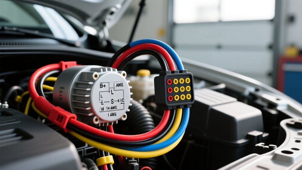
Understanding Alternator Wiring Diagrams: The Fundamentals
When upgrading a classic car or replacing a failed charging system, interpreting alternator wiring diagrams is the most critical step for beginners. A wiring schematic is not just a map; it is a functional blueprint that dictates how the voltage regulator senses battery state and excites the rotor field. This guide breaks down the fundamental differences between 1-wire and 3-wire configurations, using the ubiquitous GM 12SI and CS130 alternators as our primary teaching models.
Decoding the GM 12SI 3-Wire Alternator Diagram
The GM 12SI (System Integrated) alternator, introduced in the early 1970s, remains the gold standard for basic 3-wire charging system swaps. Understanding its alternator wiring diagram requires identifying the three primary connection points: the BAT terminal, Terminal 1 (Sense), and Terminal 2 (Exciter).
| Terminal | Function | OEM Wire Color | AWG Size | Routing Destination |
|---|---|---|---|---|
| BAT Post | Main DC Output | Red | 8 or 10 AWG | Battery Positive or Starter Solenoid |
| Terminal 1 (R) | Voltage Sense | White / Red | 18 AWG | Main Junction Block or Battery Positive |
| Terminal 2 (F) | Field Exciter | Brown | 18 AWG | Ignition Switch (via Dash Warning Light) |
The "Idiot Light" Resistor Rule
A common beginner mistake when reading 12SI alternator wiring diagrams is ignoring the exciter circuit's current requirements. The internal voltage regulator requires a small initial current to "turn on" the alternator. If your vehicle uses a dash warning light (idiot light), the bulb's filament provides this resistance. However, if your vehicle uses an aftermarket ammeter or volt gauge without a warning light, you must wire a 10-ohm, 2-watt resistor into the Terminal 2 exciter wire. Without it, the alternator will not charge until the engine is revved to 2,500+ RPM to self-excite via residual magnetism.
The GM CS130/CS144 4-Pin Connector Explained
Moving into the 1990s, GM introduced the CS (Charging System) series. The CS130 uses a 4-pin rectangular connector, which often confuses beginners looking at modern alternator wiring diagrams. Only two or three pins are typically used in standalone swaps.
- Pin S (Sense): Reads actual battery voltage. Must be wired directly to the battery positive post or main distribution block. (Typically Red/Black, 18 AWG).
- Pin L (Lamp): Controls the dash warning light and provides initial excitation. (Typically Brown/White, 18 AWG).
- Pin I (Ignition): Provides a switched 12V signal to wake up the regulator. (Typically Pink, 18 AWG).
- Pin P (Phase): Outputs an AC square wave proportional to engine RPM. Rarely used in basic automotive swaps, but critical for marine tachometers or ECU-driven electric fan relays.
1-Wire vs. 3-Wire Alternator Diagrams: Which is Better?
Many aftermarket catalogs push "1-wire" alternators as the ultimate beginner-friendly solution. While a 1-wire alternator wiring diagram is undeniably simple—requiring only a heavy output cable from the BAT post to the battery—it comes with hidden compromises.
| Feature | 1-Wire Alternator | 3-Wire Alternator |
|---|---|---|
| Wiring Complexity | Extremely Low (1 cable) | Moderate (Output + 2 sense/exciter wires) |
| Voltage Sensing | Internal (at the alternator case) | Remote (at the battery or fuse block) |
| Low-RPM Charging | Poor (requires revving to excite) | Excellent (charges immediately at idle) |
| Accessory Load Compensation | Poor (voltage drops at headlights/stereo) | Excellent (regulator compensates for wire loss) |
For a daily driver with high electrical loads (EFI, electric fans, premium audio), a 3-wire diagram is mandatory. Internal sensing on a 1-wire setup means the regulator only sees the voltage at the alternator's rear housing. If your heavy-gauge output wire experiences a 0.8V drop over its length, your battery will only receive 13.4V while the alternator thinks it is outputting a perfect 14.2V.
Wire Gauge (AWG) and Routing Specifications
Selecting the correct American Wire Gauge (AWG) is a frequent failure point. Alternator output is a continuous, high-amperage DC load, which generates significant heat. According to SAE J1171 and standard automotive electrical practices, you must size the wire based on the alternator's maximum amperage and the total length of the wire run (positive + ground return).
| Alternator Output | Wire Run (Under 5 ft) | Wire Run (5 to 10 ft) | Wire Run (Over 10 ft) |
|---|---|---|---|
| 60A - 80A | 10 AWG | 8 AWG | 6 AWG |
| 90A - 120A | 8 AWG | 6 AWG | 4 AWG |
| 130A - 160A | 6 AWG | 4 AWG | 2 AWG |
| 170A - 220A | 4 AWG | 2 AWG | 1/0 AWG |
Connector Types and Crimping Standards
Reading alternator wiring diagrams is only half the battle; executing the physical connections correctly is where most beginner builds fail. The GM 12SI uses a simple spade-terminal plug, while the CS130 utilizes a 4-pin Metri-Pack 280 series connector. Never use generic, unsealed butt connectors for alternator harnesses. The engine bay environment is subjected to extreme heat, oil mist, and high-frequency vibration.
For the main BAT output, always use heavy-duty, tinned copper ring terminals. Crimp the terminal using a hex-crimp die (not a standard pair of pliers) to ensure a gas-tight connection, and seal the barrel with dual-wall, adhesive-lined heat shrink tubing. For the 18 AWG sense and exciter wires, use OEM-style Delco Weather-Pack or Metri-Pack terminals with the appropriate cavity plugs and wire seals to prevent moisture ingress, which leads to rapid galvanic corrosion and high-resistance voltage drops.
Troubleshooting Decision Tree: Charging System Failures
When your wiring doesn't match the schematic's expected outcome, use this diagnostic tree to isolate the fault.
- Symptom: Alternator only charges after revving engine to 2,000 RPM.
- Cause: Missing or broken exciter wire (Terminal 2 / Pin L), or missing 10-ohm resistor in a dash-gauge setup.
- Fix: Verify continuity from the ignition switch to the exciter pin. Install a parallel resistor if no dash bulb is present.
- Symptom: Battery reads 14.2V at the alternator BAT post, but only 13.1V at the battery terminals with headlights on.
- Cause: 1-wire alternator using internal sensing, combined with undersized output wire or corroded battery lugs.
- Fix: Upgrade to a 3-wire diagram, routing the remote sense wire (Terminal 1 / Pin S) directly to the battery positive post.
- Symptom: Dash warning light stays illuminated even though the battery is charging at 14.0V.
- Cause: Incorrect diode trio inside the alternator, or the sense wire is reading a higher voltage than the exciter wire reference.
- Fix: Test the alternator diode trio with a multimeter in diode-test mode. Ensure the sense wire is not routed near high-current ignition wires, which can induce AC noise.
- Symptom: Alternator produces a high-pitched whine through the stereo, and headlight brightness pulses at idle.
- Cause: Excessive AC ripple voltage caused by a failed rectifier diode or a loose serpentine belt slipping on the alternator pulley.
- Fix: Set your multimeter to AC Volts. Measure between the BAT post and engine ground. A healthy alternator should show less than 50mV (0.050V) AC ripple. If it reads over 100mV, the internal rectifier bridge is failing. If the belt is tight and the diode is good, check for a poor engine-to-chassis ground strap.
Authoritative References and Further Reading
To ensure your charging system is safe and reliable, always cross-reference your specific vehicle's schematics with OEM documentation. For factory GM wiring diagrams and connector pinouts, Helm Incorporated provides the official dealer-level service manuals. For deep-dive technical analysis on alternator regulator logic and bench-testing procedures, Mad Electrical remains one of the most respected independent automotive electrical resources on the web. Always adhere to SAE J1171 standards for marine and high-vibration automotive electrical routing to prevent chafing and thermal runaway.