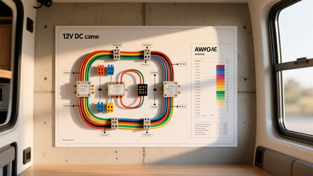
The Residential vs. Automotive Paradigm Shift
When beginners start converting a cargo van or expedition truck into a livable space, they frequently search for a 'wiring diagram for a room.' This instinct is natural, but applying residential 120V AC home wiring principles to a 12V DC automotive environment is not only inefficient—it is a severe fire hazard. A standard bedroom or living room in a house relies on alternating current (AC), high voltage, and thin 14 AWG Romex cables protected by 15-amp breakers. In contrast, the 'room' inside a Class B camper van or overland rig operates on direct current (DC), low voltage, and requires significantly thicker copper to prevent voltage drop and thermal runaway.
This guide bridges the gap between residential room wiring concepts and strict automotive electrical standards. We will break down how to design a safe, reliable 12V DC wiring diagram for your vehicle's living quarters, utilizing SAE (Society of Automotive Engineers) standards, marine-grade tinned copper, and proper overcurrent protection.
Core Differences: House AC vs. Vehicle DC
Before drawing your schematic, you must understand the fundamental physics dictating your wire sizing. In a home, power (Watts) equals Voltage x Amps. Because household voltage is high (120V), the amperage remains relatively low, allowing for thin wires. In a 12V automotive system, the voltage is roughly 1/10th of a household outlet. To deliver the same wattage, the amperage must be 10 times higher.
- Voltage Drop: In a house, a 2-volt drop over a 50-foot run is negligible. In a 12V van, a 2-volt drop represents a 16% loss of total system voltage, which will cause LED lights to flicker and compressor fridges to shut down on low-voltage protection.
- Wire Insulation: Residential NM-B (Romex) wire is rated for static, dry environments. Automotive wire must meet SAE J1128 standards, featuring cross-linked polyethylene (XLPE) insulation to withstand engine bay heat, chassis vibration, and chemical exposure.
- Grounding Topology: Houses use a dedicated neutral and ground wire back to the panel. Vehicles use the steel chassis as a common ground return path, though modern high-amperage RV builds recommend dedicated insulated ground wires back to a central busbar to prevent galvanic corrosion and ground loops.
The 12V 'Room' Wiring Diagram Layout
A proper vehicle living space schematic is divided into three distinct zones: Generation/Storage, Distribution, and Load. Below is the logical flow of your wiring diagram:
- Source: Alternator (Engine Bay) → DC-DC Charger → House Battery Bank (LiFePO4).
- Main Protection: Battery Positive → Class T Fuse (e.g., 150A) → Positive Busbar.
- Distribution: Positive Busbar → Blade Fuse Block (e.g., Blue Sea ST Blade) → Individual Room Loads (Lights, USB, Fans).
- Return Path: Individual Room Loads → Negative Busbar → Battery Negative.
SAE Wire Color Codes and AWG Sizing Chart
Never use residential wire color codes (where black is 'hot' and white is 'neutral') in a vehicle. The automotive and marine industries follow strict SAE and ABYC color conventions. Red is always positive DC, and black or yellow is negative/ground.
| AWG Size | Max Amps (Chassis) | Max Amps (Engine Bay) | SAE Color Code | Typical 'Room' Application | Max Fuse Size |
|---|---|---|---|---|---|
| 1/0 AWG | 245A | 150A | Red / Black | Battery to Main Busbar | 150A Class T |
| 4 AWG | 135A | 80A | Red / Black | Inverter Feed, DC-DC Charger | 100A ANL |
| 10 AWG | 55A | 30A | Red / Black | Main Feed to Fuse Block | 40A MAX |
| 14 AWG | 20A | 10A | Red / Black | LED Puck Lights, USB Outlets | 15A Blade |
| 16 AWG | 15A | 7A | Red / Black | Low-draw Sensors, Switches | 10A Blade |
Note: Ampacities are based on single conductors in free air at 104°F (40°C). Always use the Blue Sea Systems Circuit Wizard to calculate exact voltage drop based on your specific wire length.
Step-by-Step: Routing Power to the Living 'Room'
1. Alternator to House Battery (DC-DC Charging)
To charge your living room's battery bank while driving, you must use a DC-DC charger (like the Victron Orion-Tr Smart 12/12-30). Modern vehicle alternators use smart voltage regulation that drops voltage to 12.8V or lower to save fuel, which will never fully charge a 14.4V LiFePO4 battery.
Victron Orion Pinout & Wiring:
- B1+ (Input Positive): Connect to the vehicle's starter battery positive or alternator stud using 4 AWG SAE XLPE wire. Include an inline 40A MAXI fuse within 7 inches of the starter battery.
- B1- (Input Negative): Connect to a clean, bare metal chassis ground point near the starter. Torque to OEM specifications (typically 15-20 Nm) and coat with dielectric grease.
- B2+ (Output Positive): Route 4 AWG wire through the firewall into the living space, connecting to the house battery positive busbar.
- B2- (Output Negative): Connect to the house battery negative busbar.
- Engine Shutdown Detection (H-pin): Connect to an ignition-switched 12V source (e.g., fuse box add-a-circuit on the wiper or radio fuse) so the charger only operates when the engine is running.
2. Interior Room Distribution & Grounding
Once power enters the living 'room', it must hit a centralized distribution hub. Avoid daisy-chaining lights and outlets, a common residential practice that causes severe voltage drop in 12V systems.
- Busbar Selection: Use marine-grade, tin-plated copper busbars with M8 or M10 stainless steel studs. Tin plating prevents galvanic corrosion when used with tinned copper wire.
- Torque Specs: When securing ring terminals to the busbar, use a torque screwdriver. For M8 studs, torque to 5 Nm (44 in-lbs). Under-torquing creates high resistance and heat; over-torquing strips the threads or crushes the terminal.
- Wire Preparation: Strip wires using a precision gauge stripper. Crimp using a closed-barrel ratcheting crimper (e.g., Titan Power Crimper) and seal with 3:1 adhesive-lined heat shrink. Solder is strictly prohibited in high-vibration automotive environments per SAE standards, as it creates a rigid point that will fatigue and snap.
3. Lighting and Receptacle Wiring
For 12V LED puck lights, wire them in parallel, never in series. Run a 14 AWG positive and negative feed from the fuse block to a central junction point in the ceiling, then use 16 AWG pigtails to drop down to individual lights. If using a dimmer switch, ensure it is a PWM (Pulse Width Modulation) 12V DC dimmer wired on the positive leg. Standard residential AC dimmers will instantly destroy DC LED drivers.
Common Beginner Mistakes and Troubleshooting
When your 'room' wiring fails, the issue is almost always related to poor connections or undersized wires. Use a digital multimeter to perform a Voltage Drop Test.
- Turn on the problematic load (e.g., a dimming LED light).
- Set your multimeter to DC Volts.
- Place the red probe on the positive battery terminal and the black probe on the positive terminal of the load itself. A reading above 0.1V indicates excessive resistance in the positive wire or a bad crimp.
- Repeat on the ground side: Red probe on the load's negative terminal, black probe on the battery's negative terminal. Again, anything over 0.1V indicates a poor ground connection.
By adhering to automotive standards rather than residential habits, your vehicle's living space will remain safe, efficient, and reliable whether parked off-grid or cruising at 70 MPH. For comprehensive fire and life safety standards regarding RV electrical builds, always consult NFPA 1192 (Standard on Recreational Vehicles) before finalizing your schematic.