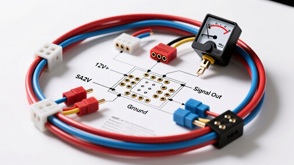
Introduction to Automotive Voltmeter Circuits
In modern and classic automotive electrical systems, a voltmeter is not merely an accessory; it is a critical diagnostic instrument. While an ammeter measures current flow, a voltmeter monitors the electrical pressure (potential difference) across the system. This is vital because modern Engine Control Units (ECUs) and CAN-bus networks rely on a stable 5V internal reference regulator, which in turn requires a clean, consistent 12V-14.4V supply. A failure in the alternator's voltage regulator or a high-resistance ground can cause cascading sensor faults. This technical specification reference provides the exact wiring diagram for voltmeter integration, covering 12V passenger vehicles and 24V heavy-duty commercial platforms, alongside SAE-compliant wire specifications and diagnostic matrices.
Standard 12V Analog Voltmeter Wiring Schematic
The standard aftermarket or OEM-style analog voltmeter utilizes a simple 3-terminal or 4-terminal configuration. The core circuit requires a switched 12V+ power source, a dedicated low-resistance chassis ground, and an illumination feed tied to the headlight switch rheostat. Because voltmeters possess high internal resistance (typically 10,000 to 50,000 ohms), they draw negligible current (under 0.5 Amps). Therefore, the primary concern in the wiring diagram for voltmeter routing is not current-carrying capacity, but rather signal integrity and voltage drop prevention.
Terminal Pinout and Wire Color Specifications
The following table outlines the standard pinout for a 3-terminal 12V analog voltmeter. Adhering to these wire color codes and AWG ratings ensures consistency with standard automotive harness repair manuals and SAE guidelines.
| Terminal | Function | Source / Destination | AWG | Standard Wire Color | Fuse Rating |
|---|---|---|---|---|---|
| IGN / + | Switched 12V Power | Ignition Switch (Run/Start) | 18 AWG | Red (with inline fuse) | 2A ATO |
| GND / - | Circuit Ground | Chassis Ground / Ground Bus | 18 AWG | Black | N/A |
| LIGHT | Illumination | Headlight Switch Rheostat | 20 AWG | White or Orange/White | Shared Circuit |
Wire Gauge, Insulation, and SAE J1128 Standards
When executing the wiring diagram for voltmeter installations, selecting the correct wire insulation is as critical as the copper gauge. According to SAE J1128 standards, low-voltage automotive cables must withstand high under-hood temperatures and chemical exposure. For instrument cluster wiring routed through the firewall, we specify GXL (General Cross-Linked) or TXL (Thin Cross-Linked) wire. TXL is preferred for modern high-density connectors due to its thinner insulation wall, while GXL offers superior abrasion resistance for harnesses routed along the chassis.
Although 18 AWG wire is rated for up to 16 Amps in chassis wiring, the voltmeter draws less than 0.5A. The use of 18 AWG is mandated not for current capacity, but for mechanical durability. Wires smaller than 18 AWG (such as 22 AWG) are highly susceptible to vibration-induced fatigue failure and terminal crimp degradation in automotive environments.
Digital Voltmeter and Heavy-Duty 24V Applications
Heavy-duty commercial trucks (e.g., Class 8 tractors, agricultural equipment) utilize dual 12V batteries wired in series to create a 24V nominal system (charging at 27.5V - 28.8V). Wiring a standard 12V voltmeter into a 24V system will instantly destroy the internal coil or digital logic board. The wiring diagram for voltmeter setups in 24V applications requires either a dedicated 24V gauge or a high-precision digital voltmeter equipped with an internal step-down resistor network or DC-DC buck converter.
24V Commercial Truck Wiring Matrix
| Parameter | 12V Nominal System | 24V Nominal System |
|---|---|---|
| Key-Off Battery Voltage | 12.4V - 12.7V | 24.8V - 25.4V |
| Alternator Charging Voltage | 13.8V - 14.4V | 27.5V - 28.8V |
| Recommended Inline Fuse | 2A - 3A ATO | 2A - 3A ATO |
| Minimum Wire Gauge | 18 AWG (TXL/GXL) | 18 AWG (TXL/GXL) |
| Maximum Acceptable Ripple (AC) | < 50mV AC | < 75mV AC |
Critical Grounding Protocols and Voltage Drop
The most common point of failure in any voltmeter wiring diagram is the ground circuit. A voltmeter measures the potential difference between its positive terminal and its negative terminal. If the ground wire is attached to a painted surface, rusted bolt, or shared with a high-current accessory (like a fuel pump), a voltage drop will occur across the ground path.
For example, if the battery is at 14.2V, but there is a 0.8V drop across a poor chassis ground, the voltmeter will read 13.4V. This false reading may lead a technician to incorrectly diagnose the alternator voltage regulator as failing. Reference the Painless Performance Wiring Manual for proper ground bus implementation. Always use a dedicated star washer to bite through the chassis metal, apply a torque of 10-15 Nm depending on the fastener size, and seal the termination with dielectric grease to prevent galvanic corrosion.
Alternator Ripple and Analog Needle Flutter
Automotive alternators produce DC voltage by rectifying a 3-phase AC output using a diode trio. This rectification process leaves a residual AC 'ripple' on the DC line. In a healthy system, this ripple is filtered by the battery and remains below 50mV AC. However, if a diode fails, or if the battery has high internal resistance, the AC ripple increases.
When wiring an analog voltmeter, excessive AC ripple will cause the electromagnetic coil inside the gauge to rapidly fluctuate, resulting in a blurred or vibrating needle. As outlined in Autometer's technical installation guides, if your analog gauge exhibits needle flutter, you must test the system with a digital multimeter set to AC Volts. If AC voltage exceeds 100mV, the root cause is an alternator or battery fault, not the gauge wiring. If the electrical system is healthy but minor flutter persists, installing a 470µF electrolytic capacitor in parallel across the gauge's power and ground terminals will act as a low-pass filter, stabilizing the needle.
Diagnostic Troubleshooting Matrix
Use the following decision tree to troubleshoot anomalies discovered after executing the wiring diagram for voltmeter circuits.
| Symptom | Probable Root Cause | Multimeter Diagnostic Test |
|---|---|---|
| Gauge reads 0.5V - 1.5V lower than battery. | High resistance in the ground circuit or shared ground bus. | Measure DC voltage between the gauge GND terminal and the battery negative post. Any reading over 0.1V indicates a bad ground. |
| Gauge reads full scale (pegged) when ignition is ON. | Internal coil short or gauge wired directly to unswitched 24V source on a 12V system. | Disconnect the gauge. Measure source voltage with a DMM. Verify it matches the system nominal voltage and drops to 0V when keyed off. |
| Analog needle vibrates or is unreadable at idle. | Excessive alternator AC ripple due to a blown rectifier diode. | Set DMM to AC Volts. Probe battery terminals. Reading > 50mV AC confirms alternator diode failure. |
| Gauge does not illuminate with parking lights. | Blown rheostat fuse, or PWM illumination circuit mismatch. | Test the illumination feed wire for 12V with parking lights on. Note: Late-model CAN-bus vehicles use PWM signals, requiring a digital interface module. |
Summary of Installation Best Practices
Executing a flawless wiring diagram for voltmeter integration requires adherence to strict electrical protocols. Always use ratcheting micro-crimp tools for 18 AWG terminals to ensure a gas-tight connection. Route the switched 12V wire through the firewall using a dedicated grommet, keeping it at least 4 inches away from high-tension ignition wires or CAN-bus twisted pairs to prevent electromagnetic interference (EMI). By treating the voltmeter not as a simple accessory, but as a precision diagnostic node, you ensure accurate monitoring of the vehicle's vital electrical health.