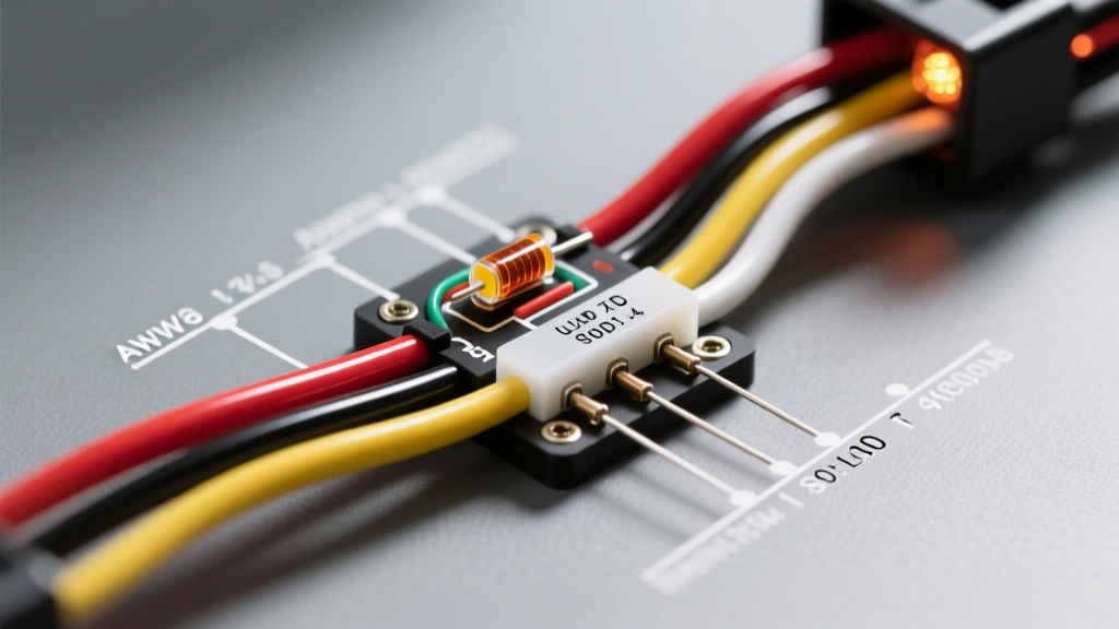
Understanding the Hyperflash Phenomenon in LED Conversions
Upgrading your vehicle's exterior lighting to LEDs is one of the most effective ways to improve visibility and modernize your car's aesthetic. However, installing LED bulbs in turn signal circuits almost universally triggers 'hyperflashing'—a rapid blinking rate that mimics a burnt-out bulb. This occurs because the Body Control Module (BCM) or thermal flasher relay monitors the circuit's current draw. A standard 1156 or 7440 incandescent bulb draws approximately 21 watts (about 1.5 to 1.75 amps). In contrast, a high-output LED turn signal bulb typically draws only 3 to 5 watts (0.25 to 0.4 amps). When the BCM detects this massive drop in amperage, it assumes the bulb has failed and doubles the flash rate to alert the driver.
To resolve this, you must install a load resistor to artificially simulate the electrical load of the factory incandescent bulb. Below is a comprehensive turn signal LED load resistor wiring diagram and installation guide, engineered for automotive electrical standards and long-term reliability.
The Electrical Theory: Why 50W 6-Ohm Resistors?
Before cutting into your factory harness, it is critical to understand the mathematical requirements of the circuit. According to SAE J573 automotive lighting standards, turn signal circuits are designed around specific resistance thresholds. Using Ohm's Law (V = IR) and the Power equation (P = V²/R), we can determine the exact resistor needed.
- System Voltage: 14.4V (alternator charging voltage)
- Target Resistance: 6 Ohms
- Current Draw: 14.4V / 6Ω = 2.4 Amps
- Heat Dissipation: (14.4V²) / 6Ω = 34.5 Watts
Because the resistor will dissipate nearly 35 watts of continuous heat while the turn signal is active, a standard 10W or 25W resistor will overheat, melt, and potentially cause a fire. You must use a 50-Watt, 6-Ohm aluminum-housed chassis mount resistor to provide adequate thermal overhead. For a deeper dive into automotive circuit calculations, refer to the Haynes Electrical System Basics guide.
Turn Signal LED Load Resistor Wiring Diagram
The load resistor must be wired in parallel with the LED bulb. This means the resistor bridges the positive turn signal wire and the negative ground wire, sitting alongside the LED bulb rather than in series with it. If wired in series, the resistor will drop the voltage, dimming your LEDs and defeating the purpose of the upgrade.
Schematic Topology
[BCM / Flasher Relay] --- (12V+ Switched Turn Signal Wire) ---+--- [LED Bulb Positive]
                                                              |
                                                      [50W 6-Ohm Resistor]
                                                              |
[Chassis Ground] ---------- (Ground Wire / Chassis) ---------+--- [LED Bulb Negative]
Required Tools and Materials
| Component | Specification | Notes / Best Practices |
|---|---|---|
| Load Resistor | 50W 6-Ohm Aluminum | Must include mounting tabs and hardware. |
| Tap Wire | 16 AWG Stranded Copper | Automotive grade (GXL or TXL) primary wire. |
| Connectors | Posi-Tap (16-18 AWG) | Avoid T-taps; they cause corrosion and strand breakage. |
| Heat Shrink | 3/16' Adhesive-Lined | Marine-grade with internal sealant for waterproofing. |
| Mounting Hardware | #10 Self-Tapping Screws | For securing resistor to bare metal chassis. |
| Testing Tool | Digital Multimeter (DMM) | Required to verify 12V+ switched wire vs. ground. |
OEM Turn Signal Wire Color Reference Chart
Wire colors vary drastically by manufacturer, model, and year. Never guess based on color alone; always verify with a multimeter. Below are common baseline wire colors for the front and rear turn signal circuits on major domestic and import platforms.
| Manufacturer | Common Front Turn Signal (+) | Common Rear Turn Signal (+) | Ground (-) |
|---|---|---|---|
| GM (Chevy/GMC) | Light Blue or Yellow | Yellow (Left) / Dark Green (Right) | Black |
| Ford (F-150/Mustang) | Light Green/Orange Stripe | Light Green/Orange or Yellow/Red | Black/Yellow Stripe |
| Toyota / Lexus | Green/White Stripe | Green (Left) / Yellow (Right) | White/Black Stripe |
| Honda / Acura | Light Green/Black | Light Green/Red or Yellow/Green | Black |
Step-by-Step Installation Guide
Step 1: Locate and Verify the Factory Wires
Gain access to the turn signal wiring harness. For front signals, this usually requires removing the wheel well liner or reaching behind the bumper cover. For rear signals, pull back the trunk carpeting or interior quarter-panel trim. Set your multimeter to DC Voltage. Back-probe the wires at the bulb connector while the turn signal is active. The wire that pulses between 0V and 12V-14V is your switched positive feed. Identify a solid chassis ground or the dedicated ground wire in the harness.
Step 2: Splice the Resistor in Parallel
Cut two lengths of 16 AWG wire (about 12 to 18 inches, depending on where you plan to mount the resistor). Strip 3/8' of insulation from the ends. Using a Posi-Tap connector, tap the resistor's positive lead into the 12V+ switched turn signal wire. Crimp the other end directly to one of the resistor's terminals. Next, tap the resistor's negative lead into the ground wire, or terminate it with a ring terminal to a clean, unpainted chassis bolt. As recommended by experts at Superbright LEDs, ensure all bare wire is covered with adhesive-lined heat shrink to prevent moisture ingress and copper oxidation.
Step 3: Thermal Management and Mounting
CRITICAL WARNING: A 50W load resistor will reach surface temperatures exceeding 300°F (150°C) during sustained use. Never mount the resistor to plastic trim, rubber weatherstripping, or directly against the wiring harness. The resistor must be mounted to a flat, bare metal surface on the vehicle's chassis to act as a heatsink. Use the included metal mounting brackets and #10 self-tapping screws. If the mounting surface is painted, sand away a 1-inch square of paint to ensure bare metal-to-metal contact for optimal heat transfer.
Step 4: System Testing and Reassembly
Before reassembling the trim panels, activate the hazard lights and let them run for 3 to 5 minutes. Carefully place your hand near (do not touch) the resistor to ensure it is dissipating heat properly and that no surrounding materials are off-gassing or melting. Verify that the LED bulbs are flashing at a normal, DOT-compliant rate (typically 60 to 120 flashes per minute). Once confirmed, secure all loose wiring with automotive Tesa tape or split loom tubing and reinstall the trim.
Troubleshooting Common Resistor Issues
| Symptom | Probable Cause | Technical Solution |
|---|---|---|
| Hyperflashing persists | Poor ground connection or high resistance in the tap. | Check ground ring terminal; sand chassis to bare metal. Verify Posi-Tap is biting through the wire insulation. |
| Resistor melting nearby plastic | Improper mounting location; lack of heatsinking. | Relocate resistor to a heavy steel chassis crossmember or suspension tower using self-tapping screws. |
| Bulb out warning on dash (CANBUS) | BCM requires specific digital handshake, not just raw amperage. | Resistors alone won't fix CANBUS errors on modern European cars (BMW/Audi). Install inline CANBUS decoders instead. |
| Turn signals stay on solid (no flash) | Short circuit or BCM thermal protection triggered. | Inspect wiring for pinched 12V+ wire grounding out. Check inline fuses. |
Final Considerations for LED Upgrades
While load resistors are the most cost-effective method to cure hyperflashing, they inherently negate the energy-saving benefits of LED bulbs by converting excess electrical energy into heat. If you are performing a complete vehicle lighting overhaul, consider upgrading to an electronic LED flasher relay (if your vehicle uses a traditional 3-pin or 2-pin relay layout) or utilizing LED bulbs with integrated, built-in resistors. However, for modern vehicles where the BCM controls the flash rate directly via solid-state switching, the parallel turn signal LED load resistor wiring diagram detailed above remains the gold standard for a reliable, error-free installation.