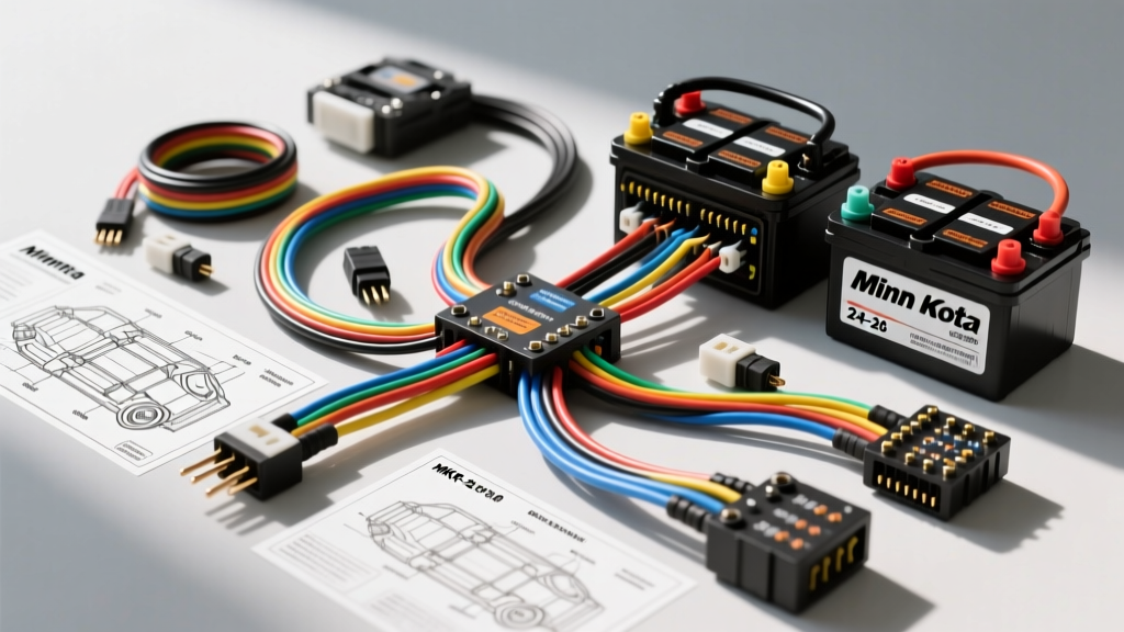
Project Overview: Upgrading to a 24-Volt Minn Kota System
Transitioning from a 12-volt to a 24-volt electrical architecture is one of the most impactful modification projects you can undertake for custom marine, off-road, or truck-bed camper setups. When consulting a Minn Kota wiring diagram 24 volt schematic, the primary goal is to double the available voltage to support high-thrust trolling motors (typically 70 lbs to 112 lbs of thrust) while halving the amperage draw compared to a 12V equivalent. This reduction in current minimizes voltage drop, decreases heat generation in the wiring harness, and significantly extends runtime on the water or trail.
This comprehensive upgrade guide covers the exact series battery bank configuration, ABYC-compliant wire gauge sizing, Minn Kota MKR-26 and MKR-20 receptacle pinouts, and critical charging system modifications required to execute a flawless 24-volt installation.
The 24-Volt Series Battery Bank Configuration
To achieve 24 volts, you must wire two identical 12-volt deep-cycle batteries (AGM, Gel, or LiFePO4) in series. In a series circuit, voltage is additive, but the amp-hour (Ah) capacity remains the same as a single battery. It is an absolute rule in marine electrical engineering that both batteries must be of the exact same chemistry, age, and capacity to prevent parasitic drain and premature cell failure.
Series Wiring Logic
- Battery 1 (B1) Negative: Connects to the main system ground bus or the negative terminal on the trolling motor plug.
- Series Jumper: A heavy-gauge cable connects B1 Positive to Battery 2 (B2) Negative. This jumper must be the exact same AWG and length as the main positive and negative run cables to maintain balanced resistance.
- Battery 2 (B2) Positive: Connects to the main 24V positive output, passing through the primary circuit breaker before reaching the receptacle.
ABYC & SAE Wire Gauge Sizing Chart
Standard automotive primary wire is strictly prohibited in marine and high-moisture environments. Per SAE J378 and UL 1426 standards, you must use marine-grade, tinned copper wire (Type 3 stranding) to resist galvanic corrosion and vibration fatigue. The following chart dictates the minimum AWG size based on the motor's maximum amp draw and the total round-trip wire length (from the battery bank to the motor receptacle and back).
| Motor Thrust | Max Amp Draw | Round-Trip Length (Under 15 ft) | Round-Trip Length (15 - 20 ft) | Round-Trip Length (Over 20 ft) |
|---|---|---|---|---|
| 70 lbs | 42 Amps | 8 AWG | 6 AWG | 4 AWG |
| 80 lbs | 56 Amps | 6 AWG | 4 AWG | 2 AWG |
| 101 lbs | 60 Amps | 6 AWG | 4 AWG | 2 AWG |
| 112 lbs | 65 Amps | 4 AWG | 2 AWG | 1/0 AWG |
Minn Kota 24-Volt Plug and Receptacle Pinout
Understanding the receptacle pinout is where most DIY upgrades fail. Minn Kota primarily utilizes the MKR-26 (3-wire) for dedicated 24V systems and the MKR-20 / MKR-19 (4-wire) for systems that require both 12V and 24V outputs (useful for running a 12V livewell or fish finder alongside the 24V motor). Below is the definitive pinout for the 4-wire 24V/12V receptacle, which is the gold standard for custom modification projects.
4-Wire Receptacle Pin Configuration (MKR-20 Style)
| Pin Letter | Function | Wire Color | Battery Bank Connection |
|---|---|---|---|
| Pin A | 24V Positive | Red | B2 Positive (via 60A Breaker) |
| Pin B | 12V Positive | White or Orange | B1 Positive (via 50A Breaker) |
| Pin C | 12V / 24V Common Ground | Black | B1 Negative |
| Pin D | 12V Negative (Isolated) | Black | B1 Negative (Jumpered to Pin C) |
Expert Note: When wiring the male plug on the trolling motor side, ensure you are referencing the mirror-image diagram. Pin A on the receptacle mates with Pin A on the plug, but the physical orientation is reversed when looking at the face of the connectors.
Circuit Protection and Breaker Sizing
According to ABYC E-11 AC & DC Electrical Systems on Boats, every ungrounded current-carrying conductor must be protected by a circuit breaker or fuse located within 7 inches of the power source. For a 24V Minn Kota upgrade, you must use marine-rated, ignition-protected (SAE J1171) resettable circuit breakers.
- 50-Amp Breaker: Required for the 24V positive lead on motors rated up to 80 lbs of thrust.
- 60-Amp Breaker: Mandatory for high-draw motors like the Ultrex or Fortrex 112 lb thrust models.
- 12V Accessory Breaker: If utilizing Pin B for a 12V accessory, install an inline 30A or 40A breaker on the B1 Positive lead, depending on the accessory load.
Alternator Charging Modifications for 24V Banks
A critical oversight in 24V upgrade projects is attempting to charge the series battery bank with a standard 12V marine alternator. Wiring a 12V alternator directly to B1 will severely overcharge the first battery while leaving B2 completely depleted, ultimately destroying both batteries and potentially causing a thermal runaway event.
To properly charge a 24V series bank from a 12V alternator, you must install a high-amperage 12V-to-24V DC-DC charger (such as the Victron Energy Orion-Tr Smart 12/24). Wire the input of the DC-DC charger to your engine's starting battery, and wire the output across the entire 24V series bank (B1 Negative to B2 Positive). The DC-DC charger will intelligently step up the voltage and manage the bulk, absorption, and float stages for both batteries simultaneously, ensuring perfect equilibrium.
Step-by-Step 24V Upgrade Execution
- Prepare the Terminals: Strip the marine-grade wire using a precision wire stripper. Do not nick the tinned copper strands.
- Crimp and Seal: Use a heavy-duty hex-crimp tool to attach marine-grade, adhesive-lined heat shrink ring terminals. Apply heat until the adhesive sealant purges from the edges, creating a watertight barrier against galvanic corrosion.
- Mount the Breakers: Secure the 60A and 50A resettable breakers to a non-conductive, fire-retardant panel within 7 inches of the battery bank positive terminals.
- Wire the Receptacle: Route the 4 AWG or 2 AWG cables to the bow or deployment location. Terminate the wires into the MKR-20 receptacle using the pinout chart above. Apply dielectric grease to the receptacle pins before mating.
- Torque Specifications: When securing the heavy-gauge lugs to the battery terminals, use a calibrated torque wrench. The standard torque spec for a 3/8-inch battery terminal nut is 96 to 120 in-lbs (8 to 10 ft-lbs). Overtightening will strip the lead post; undertightening will cause high-resistance arcing.
Troubleshooting Voltage Drop & Ground Faults
Even with a perfect Minn Kota wiring diagram 24 volt reference, environmental factors can introduce resistance. If your motor is losing power or the breaker is tripping prematurely, perform a voltage drop test.
The 3% Voltage Drop Rule
Set your digital multimeter to DC Volts. Place the positive probe on the B2 Positive battery terminal and the negative probe on the corresponding Pin A at the bow receptacle (with the motor running under load). On a 24V system, the maximum allowable voltage drop is 3%, which equates to 0.72 volts. If your multimeter reads a drop greater than 0.72V, you have excessive resistance.
Common Failure Modes and Fixes
- Corroded MKR-26 / MKR-20 Pins: The male and female plug connections are the most common failure points. Pull the plug, inspect for green copper oxide, clean with electrical contact cleaner, and re-apply marine dielectric grease.
- Undersized Series Jumper: If the jumper wire connecting B1 Positive to B2 Negative is smaller than the main run cables, it will act as a bottleneck, generating heat and choking amperage to the motor. Replace it with matching AWG wire.
- Loose Wingnuts: Hand-tightened wingnuts on battery terminals vibrate loose on rough water. Replace all wingnuts with stainless steel hex nuts and torque them to spec.
By adhering strictly to these ABYC standards, SAE wire specifications, and Minn Kota pinout configurations, your 24-volt upgrade will deliver reliable, high-thrust performance for years to come.