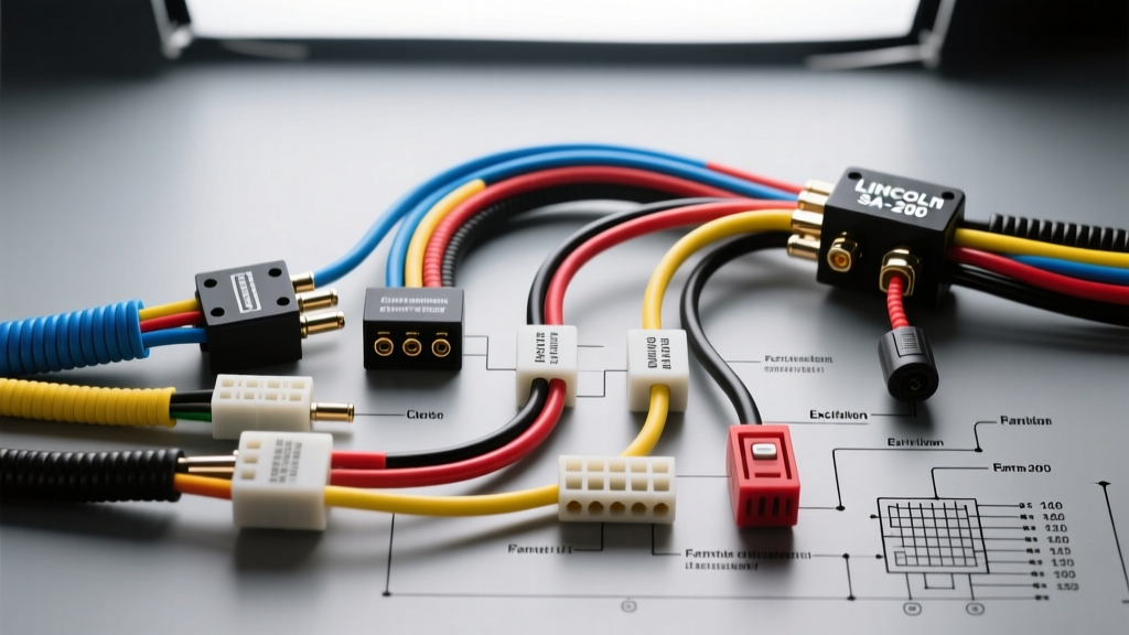
Architectural Overview of the SA-200 Electrical System
The Lincoln Electric SA-200 is a cornerstone of pipeline and heavy-industry welding. While technically a welding power source, when skid-mounted on a service truck (such as a Ford F-550 or Freightliner M2), its electrical architecture becomes deeply integrated with the host vehicle's Power Take-Off (PTO), high-idle solenoids, and upfitter modules. Understanding the complete wiring diagram for Lincoln SA-200 units requires analyzing three distinct circuits: the internal excitation/stator control, the remote pendant interface, and the host vehicle PTO integration.
Unlike modern inverter machines, the classic SA-200 (Codes 8408, 8510, and early 10000-series) utilizes a rotating armature design with slip-ring excitation. This means the main welding current is generated in the rotor, while the exciter field is stationary. Misinterpreting this architecture is the leading cause of miswiring during engine swaps or control board upgrades. For comprehensive OEM schematics, technicians should always cross-reference the Lincoln Electric Service Manuals database to verify code-specific revisions.
Excitation and Stator Control Circuit Analysis
The excitation circuit dictates the Open Circuit Voltage (OCV) and the overall amperage output. In the SA-200, the exciter stator field is energized by a separate exciter generator or a solid-state PCB (depending on the exact manufacturing year and code). The current control rheostat is wired in series with the exciter field to vary the magnetic flux.
Stator and Exciter Wire Routing Specifications
| Wire ID | Color | AWG | Function | Termination Point |
|---|---|---|---|---|
| #10 | Red | 10 AWG | Exciter Field Positive | PCB / Rheostat Output |
| #11 | Black | 10 AWG | Exciter Field Negative | Exciter Stator Return |
| #14 | White | 14 AWG | Main Stator Sense | PCB Voltage Feedback |
| #15 | Green | 14 AWG | Exciter AC Input | PCB Rectifier Bridge |
Technical Note on Slip Rings: The excitation current is transferred to the rotating armature via two copper slip rings. A common failure mode is carbon dust tracking across the insulating barrier between the rings, causing a partial short. When servicing, blow out the slip ring housing with low-pressure dry air (max 30 PSI) and verify brush spring tension is between 2.0 and 3.0 PSI using a fish scale. Morganite CM1S or equivalent electrographitic brushes are required to prevent excessive ring wear.
Remote Pendant Wiring Diagram & Pinout Table
Field operators rely on remote pendants to adjust amperage and voltage without returning to the rig. The SA-200 typically utilizes a heavy-duty mil-spec Amphenol MS3106A circular connector (often 14-pin or 6-pin configurations) to interface with dual-schedule remote control boxes (e.g., Lincoln K935 or K165). Strain relief on these connectors is critical; always use aDeutsch or Amphenol backshell with a molded rubber boot to prevent wire fatigue at the solder cups.
14-Pin Amphenol MS3106A-20-29P Pinout
- Pin A & B: Voltage Control Potentiometer (10kΩ linear taper). 18 AWG shielded twisted pair.
- Pin C & D: Amperage Control Potentiometer (10kΩ linear taper). 18 AWG shielded twisted pair.
- Pin E: Common Ground for remote circuit (Tied to chassis ground at PCB).
- Pin F & G: Contactor / Weld Output Enable (12V DC coil trigger). 14 AWG.
- Pin H: Auto-Idle Override Switch (Pull to ground to force high idle). 16 AWG.
When fabricating replacement remote cords, use 14/7 SOOW (Service, Oil, Outdoor, Weather-resistant) heavy-duty rubber-jacketed cable. Standard PVC trailer wire will crack and fail within weeks in pipeline right-of-way conditions.
Host Vehicle Integration: PTO and Idle-Up Wiring
Integrating the SA-200 with a modern diesel service truck requires bridging the truck's Engine Control Module (ECM) or Upfitter Interface Module (UIM) with the welder's auto-idle solenoid. Modern trucks (like the Ford F-Series Super Duty with the PTO prep package) utilize multiplexed CAN-bus signals rather than simple 12V discrete outputs. To safely wire the truck to the SA-200 without backfeeding the truck's ECM, an isolation relay harness is mandatory.
Isolation Relay Harness Specifications
Use a Littelfuse 24063 (12V, 40A) heavy-duty continuous duty relay to isolate the truck's PTO trigger from the welder's idle solenoid.
- Relay Terminal 30 (Input): Connect to the truck's dedicated Upfitter battery feed using 10 AWG red wire with a 30A MIDI fuse within 6 inches of the battery.
- Relay Terminal 87 (Output): Connect to the SA-200 idle-up solenoid positive terminal using 12 AWG blue wire.
- Relay Terminal 86 (Coil +): Connect to the truck's PTO/Upfitter switch output (typically 14 AWG green). Verify this circuit provides a true 12V+ under load, not a PWM or multiplexed signal. If using a Ford UIM, consult the SAE J1292 Automobile Electrical Systems guidelines for proper upfitter relay isolation.
- Relay Terminal 85 (Coil -): Connect to a dedicated chassis ground point using 14 AWG black wire. Torque the ground lug to 18 lb-ft and apply dielectric grease to prevent galvanic corrosion.
Engine Governor Note: If the SA-200 is powered by a Cummins B-Series or Cummins ISC industrial engine (common in older skid mounts), the idle solenoid is a simple pull-type 12V DC coil. However, if mounted on a truck utilizing the truck's own engine to drive a hydraulic PTO pump for a welder, the idle-up signal must be routed through the truck's OEM PTO enable switch to satisfy ECM safety interlocks.
Troubleshooting Common SA-200 Electrical Failures
When diagnosing a 'No Weld Output' or 'Low OCV' condition on the SA-200, follow this structured decision tree before replacing major components:
Diagnostic Decision Tree: Low Open Circuit Voltage (OCV)
- Check Residual Magnetism: If the machine has sat idle for months, the exciter field may have lost residual magnetism. Fix: Flash the field by momentarily applying 12V DC from the truck battery to wires #10 (Positive) and #11 (Negative) while the engine is running at low idle.
- Measure Exciter Field Resistance: Disconnect wires #10 and #11 at the PCB. Measure resistance across the exciter stator terminals. Spec: Should read between 15Ω and 25Ω. If reading infinite (OL), the exciter field winding is open and requires rewinding.
- Inspect the Rheostat: Measure the resistance of the front-panel current control rheostat. Spec: Should sweep smoothly from 0Ω to ~100Ω. Erratic multimeter readings indicate worn carbon tracks inside the potentiometer, requiring immediate replacement to prevent arc-burning the exciter diodes.
- Verify Slip Ring Continuity: Measure resistance directly across the copper slip rings on the rotor shaft. Spec: Typically 0.5Ω to 1.5Ω. A reading above 5Ω indicates severe brush pitting or a loose internal rotor lead connection.
Final Torque and Assembly Specifications
Proper termination is just as critical as correct routing. Vibration from the host truck's diesel engine and the welder's own rotating mass will loosen improperly torqued lugs, leading to high-resistance hotspots and eventual PCB burnout.
- PCB Terminal Screws: Torque to 15 in-lbs. Use a split-ring lock washer and a flat washer under all spade terminals.
- Stator Output Lugs (4/0 AWG): Torque to 25 lb-ft. Apply No-Ox-Id 'A-Special' conductive grease to the copper-to-copper mating surfaces to prevent oxidation in high-humidity environments.
- Amphenol Connector Backshell: Hand-tighten plus 1/8 turn with spanner wrench. Do not overtighten, as this will crush the internal rubber grommet and compromise the IP67 weather seal.
By adhering to these precise wiring schematics, AWG requirements, and diagnostic protocols, fleet technicians and rig owners can ensure the Lincoln SA-200 operates reliably in the harshest mobile environments.