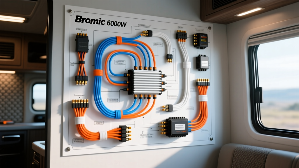
Expedition Vehicle Architecture for 6000W Auxiliary Heating
Integrating a high-output Bromic 6000W heater into an expedition RV, custom camper van, or heavy-duty service truck requires a flawless DC-to-AC electrical architecture. Unlike standard 12V diesel air heaters, a 6000W AC infrared or forced-air unit demands massive current from the vehicle's secondary battery bank. Running a 6000W continuous load on a 24V DC system requires a sustained draw of roughly 250 Amps, pushing the absolute limits of standard automotive wiring. This guide provides a step-by-step troubleshooting flow for the vehicle-side wiring diagram, focusing on inverter feeds, Battery Management System (BMS) relays, and heavy-duty DC cabling.
Phase 1: DC Feed and Inverter Input Troubleshooting
The most common failure point in high-wattage RV heater diagrams is voltage drop between the lithium battery bank and the pure sine wave inverter (e.g., Victron MultiPlus or Quattro series). When the Bromic heater engages, a poor DC connection will cause the inverter to trigger a low-voltage cutoff, shutting down the heater immediately.
Step 1: Inspect 4/0 AWG Cabling and Lugs
For a 24V system delivering 6000W, you must use 4/0 AWG welding cable (compliant with SAE J1128 Low Tension Primary Cable standards). If the system is 12V, parallel 4/0 AWG runs are mandatory, though a 6000W load on 12V (500A+) is highly discouraged due to extreme heat generation.
- Visual Inspection: Check all M8 and M10 ring terminals for discoloration. A blue/black hue on the copper indicates thermal overload from a loose crimp.
- Hydraulic Crimp Verification: Hand-crimped lugs will fail under 250A loads. Ensure a 12-ton hydraulic crimper with the correct hex die was used.
- Voltage Drop Test: With the Bromic heater running at maximum output, place multimeter probes directly on the battery busbar and the inverter DC input terminal. A voltage drop greater than 0.5V DC indicates undersized wire, excessive cable length, or high resistance at the Class T fuse block.
Step 2: Verify Class T Fusing and Busbar Torque
Standard ANL fuses are insufficient for the high fault currents of a 6000W inverter setup. The wiring diagram must specify a 300A to 400A Class T fuse located within 18 inches of the battery positive terminal. Use a calibrated torque wrench to verify busbar connections. Loose busbar bolts create arc faults that can ignite surrounding insulation.
Phase 2: Ignition Trigger and BMS Relay Flow
To prevent the Bromic heater from draining the house bank while the vehicle is parked, the inverter's remote on/off terminal must be wired to a BMS relay or the vehicle's ignition upfitter circuit.
Step 1: Trace the 12V Trigger Wire
In a Mercedes Sprinter (VS30) or Ford Transit build, the trigger wire is typically an 18 AWG Blue/White or Violet/White wire routed from the chassis upfitter switch panel to the inverter's remote control port.
- Sprinter N10/8 Relay Block: If tapping the OEM ignition sense, verify the pinout at the N10/8 block under the driver's seat. Pin 4 (Terminal 15) provides switched 12V. Ensure a 2A inline fuse is installed on this 18 AWG trigger wire to protect the OEM multiplex module.
- BMS Relay Logic: Many expedition rigs use the BMS to control a heavy-duty 12V automotive relay (e.g., Bosch 0 332 014 150). If the heater won't turn on, test for 12V at the relay coil (pins 85 and 86) while the ignition is on. If the coil has 12V but the load side (pins 30 and 87) lacks continuity, the relay contacts are welded or burnt.
Step 2: RJ45 Remote Panel Pinout Diagnostics
If using a Victron inverter, the remote on/off is controlled via an RJ45 connector. According to the Victron Wiring Unlimited guide, pins 3 and 7 are used for the remote switch. A break in this low-voltage CAT5e cable will prevent the inverter from passing AC power to the heater's dedicated breaker panel.
Phase 3: AC Output and Heater Element Diagnostics
Once DC power and trigger logic are verified, troubleshoot the 240V AC side of the wiring diagram. A 6000W Bromic heater operating at 240V AC draws exactly 25 Amps. This requires 10 AWG THHN stranded wire routed through flexible liquid-tight conduit, protected by a 30A double-pole GFCI breaker compliant with NFPA 1192 RV Electrical Standards.
Step 1: Continuity and Resistance Testing
Disconnect the heater from the AC panel. Set your multimeter to Ohms (Ω). Measure across the Line 1 and Line 2 terminals of the heater's internal terminal block. A 6000W element at 240V should read approximately 9.6 Ω. If the meter reads 'OL' (Open Line), the internal thermal cutoff fuse has blown, or the quartz/ceramic heating element is fractured.
Step 2: Neutral and Ground Integrity
While many 240V European-style heaters do not require a neutral, North American 120V/240V split-phase setups do. Ensure the AC ground (Green/Yellow) is bonded to the vehicle's chassis ground via a dedicated copper grounding strap. A floating ground in a mobile environment can cause the heater's internal logic board to fail due to static buildup and inverter high-frequency noise.
Wiring Specification & Torque Chart
| Circuit Segment | Wire Gauge (AWG) | Max Continuous Amps | Hardware / Terminal | Torque Spec (Nm) |
|---|---|---|---|---|
| Battery to Fuse | 4/0 AWG (Red) | 285A | 3/8" Stud / M10 Ring | 12.0 Nm |
| Fuse to Inverter DC+ | 4/0 AWG (Red) | 285A | Inverter M8 Busbar | 10.0 Nm |
| Inverter AC Out (L1/L2) | 10 AWG THHN | 30A per leg | Wago 221 Lever Nut | N/A (Lever) |
| Chassis Ground Bond | 6 AWG (Green) | N/A (Fault path) | Stainless Steel Bolt | 8.5 Nm |
| Ignition Trigger | 18 AWG (Blue/White) | 2A | OEM Spade / Posi-Tap | N/A |
Symptom-Cause-Fix Decision Tree
| Symptom | Probable Cause | Diagnostic Fix |
|---|---|---|
| Heater clicks on, then immediately shuts off. | Inverter Low Voltage Cutoff (LVC) triggered by massive voltage sag. | Check 4/0 AWG crimps. Replace undersized DC cables. Verify battery BMS is not limiting output to 150A. |
| Heater receives no power; Inverter screen is blank. | Blown Class T fuse or tripped BMS main contactor. | Test Class T fuse with multimeter for continuity. Check BMS Bluetooth app for cell-level low-voltage disconnect. |
| Heater blower motor runs, but no heat is generated. | Internal thermal fuse blown or AC contactor failure inside the heater. | Test heating element for 9.6 Ω resistance. Inspect internal relay board for burnt solder joints. |
| GFCI breaker trips instantly upon heater startup. | Moisture ingress in exterior heater housing or inverter high-frequency ground leak. | Megger test the AC cables. Ensure inverter neutral-to-ground bonding relay is functioning correctly. |
Final Safety Protocols for High-Draw Mobile Systems
When working with the Bromic 6000W heater wiring diagram, always utilize a thermal imaging camera (such as a FLIR ONE) after the first 30 minutes of continuous operation. Scan all DC busbars, Class T fuse caps, and inverter terminals. Any connection exceeding 140°F (60°C) requires immediate shutdown, re-crimping, and the application of dielectric grease. Proper execution of this wiring diagram ensures safe, reliable auxiliary heating in the most extreme overlanding environments.