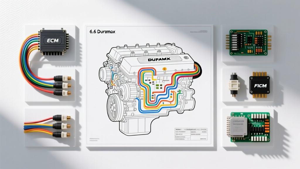
Introduction to the 6.6L Duramax Electrical Architecture
The 6.6L Duramax V8 (spanning RPO codes LB7, LLY, LBZ, LMM, LML, and L5P) represents one of the most robust diesel platforms in the light-duty truck segment. However, as these engines accumulate mileage and endure harsh thermal cycles, the electrical architecture frequently becomes the primary point of failure. Understanding the 6.6 Duramax engine wiring diagram is absolutely critical for diagnosing injector circuit faults, CAN-bus communication drops, and sensor signal degradation. This comprehensive walkthrough dissects the core Engine Control Module (ECM) pinouts, injector harness routing, and critical sensor circuits, providing actionable, bench-tested data for automotive technicians and advanced DIYers.
Core ECM Pinout Configurations and Connector Specs
The Engine Control Module on early-to-mid generation Duramax engines (specifically the LB7 and LBZ) utilizes a multi-connector setup, primarily relying on the 80-way X1 and X2 connectors. These ECM connectors utilize the Delphi Metri-Pack 280 series terminals, which are designed for high-vibration environments but are susceptible to terminal spread if improperly probed. When back-probing these circuits for oscilloscope or multimeter testing, always use a proper terminal test probe (such as the Lisle 39800 or equivalent) to avoid deforming the female terminals. A spread terminal will cause an intermittent high-resistance fault that is notoriously difficult to diagnose.
| Pin | Wire Color | AWG | Circuit Function | Diagnostic Notes |
|---|---|---|---|---|
| 1 | Pink/Black | 14 | Ignition 1 Voltage | Must read within 0.5V of battery voltage during cranking. |
| 12 | Dark Blue/White | 18 | CAN High (J1939) | Recessive: 2.5V, Dominant: 3.5V. Shielded twisted pair. |
| 13 | Dark Blue/Black | 18 | CAN Low (J1939) | Recessive: 2.5V, Dominant: 1.5V. Check for short to ground. |
| 40 | Black/White | 14 | Main ECM Ground | Voltage drop must be <0.05V under heavy electrical load. |
| 55 | Red/White | 14 | Battery Positive (Hot) | Constant 12V. Feeds ECM memory and security modules. |
Fuel Injector Harness & FICM Wiring: LB7 vs. LLY/LBZ
The most significant divergence in the 6.6 Duramax engine wiring diagram occurs in the fuel injection circuits between the LB7 and the subsequent LLY/LBZ generations.
The LB7 Direct-Fire Architecture
The LB7 (2001-2004) utilizes a direct-fire ECM architecture. The ECM contains the internal driver modules that send high-current pulses directly to the injectors. Because of this, the injector harness wires are heavier, typically 14 AWG, to handle the amperage spike which can reach up to 20 amps during the pilot injection phase. A well-documented failure mode on the LB7 is the chafing of the injector harness where it passes beneath the valve cover and rests against the aluminum cylinder head casting. The insulation degrades from heat and vibration, leading to a short to ground. Because these circuits carry high current, splicing the 14 AWG wire under the valve cover is not recommended; the entire under-cover harness must be replaced to prevent localized resistance and subsequent injector misfire codes (P0201-P0208).
The LLY/LBZ FICM Architecture
The LLY and LBZ engines introduced the Fuel Injection Control Module (FICM). This module requires massive current to charge its internal capacitors, demanding dual 8 AWG power feeds and dual 8 AWG grounds directly from the battery and engine block. The FICM then steps up the voltage (often exceeding 100V internally) to drive the injectors. The wiring diagram for the FICM-to-injector harness utilizes 16 AWG wires. If you are diagnosing a 'FICM Sync Loss' or U-codes, you must check the 8 AWG power lugs at the FICM for corrosion. Perform a dynamic voltage drop test on these main power feeds; a drop exceeding 0.1V under cranking load indicates a failing lug or internal harness corrosion.
Critical Sensor Circuits: CKP, CMP, and MAP
The Crankshaft Position (CKP) and Camshaft Position (CMP) sensors are Hall-effect devices requiring a 5V reference, a low-reference ground, and a signal return. The GM wiring schematic specifies an 18 AWG shielded twisted-pair for the signal circuits to prevent electromagnetic interference (EMI) from the high-current injector wires routed nearby. The shield drain wire must be grounded exclusively at the ECM breakout, never at the sensor pigtail. If the CKP signal drops out due to EMI or a broken wire, the engine will stall instantly without setting a hard DTC. Inspect the CKP harness near the bellhousing, where engine movement, heat, and road debris frequently compromise the split-loom conduit.
The Manifold Absolute Pressure (MAP) sensor utilizes a standard 3-wire GM configuration (5V Ref, Signal, Low Ref) with 20 AWG wiring. A common failure point is the MAP sensor pigtail connector, where oil vapor from the crankcase ventilation system ingresses into the Weather-Pack seal, creating a high-resistance path on the 5V reference circuit and causing severe under-boost conditions.
SAE J1939 CAN-Bus Diagnostics
The Duramax relies heavily on the SAE J1939 CAN-bus network for ECM-to-TCM (Transmission Control Module) communication, which is vital for shift points and torque management. The physical layer consists of a twisted pair (CAN High and CAN Low) with 120-ohm terminating resistors located at the ECM and the instrument cluster. According to SAE J1939 standards, the bus must maintain specific voltage thresholds to remain operational. When diagnosing a U0100 (Lost Communication with ECM) code, disconnect the batteries and measure the resistance across the OBD-II port pins 6 (CAN High) and 14 (CAN Low). You should read exactly 60 ohms. If you read 120 ohms, one of the terminating resistors or the wiring harness leading to it is open.
Troubleshooting Decision Tree: Engine Cranks But No Start
When utilizing the 6.6 Duramax engine wiring diagram to diagnose a no-start condition with no injector pulse, follow this structured diagnostic path:
- Step 1: Verify FICM/ECM Power. Check the main ignition relays in the underhood fuse block. Measure voltage at the ECM X1 Pin 1 (Pink/Black) during cranking. It must not drop below 10.5V.
- Step 2: Check CKP/CMP Sync. Connect an oscilloscope to the CKP and CMP signal wires. Verify that the ECM is receiving a clean 0-5V square wave and that the sync window aligns correctly. If the signal is missing, check the 5V reference circuit for a short to ground (often caused by a failed MAP or boost sensor pulling the 5V bus down).
- Step 3: Inspect CAN-Bus Integrity. If the ECM cannot communicate with the immobilizer or TCM, it will inhibit fuel delivery. Verify the 60-ohm resistance across the CAN network as described above.
- Step 4: Injector Circuit Continuity. For LB7 engines, measure injector coil resistance at the ECM connector. Specification is typically 0.2 to 0.5 ohms. For LLY/LBZ, check the FICM-to-injector harness for continuity and ensure the FICM logic power fuse is intact.
Authoritative References
For deeper schematic analysis and torque specifications for electrical connectors, consult the following resources:
- SAE J1939 CAN Bus Standards and Network Topology - Society of Automotive Engineers.
- Delphi Diesel Fuel Injection Systems - Technical documentation on common rail injector driver circuits and FICM logic.
- Haynes GM Full-Size Pick-Ups Repair Manual - Comprehensive chassis-to-engine wiring harness routing and ground location maps.