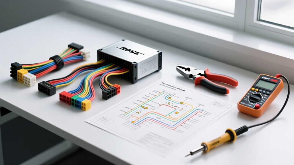
The Complexity of Bose Audio Integration
When advanced DIYers and mobile electronics technicians search for a bose factory amp wiring diagram pdf, they are typically facing a critical integration hurdle. Unlike standard automotive audio systems that use single-ended, unbalanced audio signals and 4-ohm speakers, Bose premium audio systems utilize balanced differential audio signaling and low-impedance (typically 2-ohm or 1-ohm) speaker loads. Attempting to bypass or replace a failed Bose amplifier without understanding these proprietary electrical characteristics inevitably leads to blown aftermarket amplifiers, severe alternator whine, or total data-bus communication failures.
This guide provides a comprehensive cost and tool requirements analysis for diagnosing, repairing, or bypassing a factory Bose amplifier, using the ubiquitous GM GMT900 platform (Chevy Silverado/GMC Sierra) as our primary technical reference.
Cost Analysis: OEM Repair vs. Aftermarket Bypass
Before cutting a single wire, it is vital to weigh the financial implications of your integration strategy. Bose amplifiers are not simple signal boosters; they contain internal crossovers, active noise cancellation (ANC) circuitry, and data-bus transceivers. Below is a cost breakdown of the three primary paths you can take when a factory Bose amp fails.
| Integration Strategy | Estimated Parts Cost | Estimated Labor/Time | Pros & Cons |
|---|---|---|---|
| OEM Dealer Replacement | $650 - $1,100 | $150 (1.5 hrs) | Pro: Plug-and-play, retains ANC. Con: High cost, proprietary part sourcing. |
| Aftermarket DSP Bypass Harness | $180 - $350 | $250 (3-5 hrs) | Pro: Allows custom amp/sub installation. Con: Requires replacing all 2-ohm door speakers. |
| Custom Line Output Converter (LOC) | $80 - $150 | $150 (2-3 hrs) | Pro: Lowest upfront cost. Con: High risk of impedance mismatch and thermal failure. |
Note: If you choose the bypass route, you must factor in the cost of replacing the factory 2-ohm Bose speakers with standard 4-ohm aftermarket components. Feeding a 2-ohm load into a standard aftermarket 4-ohm amplifier will cause the amp to overheat, trigger thermal protection, or suffer catastrophic output stage failure.
Essential Tool Requirements for Bose Wiring
Standard wire strippers and a basic test light are entirely insufficient for tracing Bose wiring schematics. Because Bose systems rely on Class 2 serial data (or CAN-bus on newer models) for turn-on signals and balanced differential audio for noise rejection, you must invest in diagnostic tools capable of reading high-frequency data and out-of-phase waveforms.
1. Automotive Oscilloscope (e.g., PicoScope 4225A)
- Estimated Cost: $450 - $600
- Application: Verifying balanced differential audio inputs and decoding Class 2 serial data packets.
- Why it is required: A multimeter cannot read the 10.4 kbps Class 2 data stream that tells the Bose amp to wake up. Furthermore, an oscilloscope allows you to verify that the Left Front + and Left Front - audio signals are exactly 180 degrees out of phase. If they are not, your bypass LOC will sum the signals incorrectly, resulting in phase cancellation and hollow-sounding midrange frequencies.
2. True-RMS Digital Multimeter (e.g., Fluke 87V)
- Estimated Cost: $400 - $450
- Application: Measuring speaker voice coil resistance and checking data-line shorts.
- Why it is required: You must verify that the factory Bose speakers measure between 1.8 and 2.2 ohms before deciding to retain them. The Fluke 87V's low-impedance (LoZ) mode is also critical for identifying ghost voltages on the Bose data lines caused by capacitive coupling.
3. Breakout Harnesses & Soldering Station
- Estimated Cost: $120 - $180
- Application: Non-destructive testing and permanent, low-resistance splices.
- Why it is required: T-taps and scotch locks are strictly prohibited on balanced audio and data lines. They introduce resistance and alter the capacitance of the wire, which can corrupt the Class 2 data signal and cause the Body Control Module (BCM) to throw U-codes (e.g., U1000 - Class 2 Communication Lost).
Decoding the Diagram: GMT900 Bose Pinout Reference
When reviewing your bose factory amp wiring diagram pdf, you will typically encounter two main connectors at the amplifier: a 24-pin connector for audio inputs/outputs and a 16-pin connector for power, ground, and data. Below is the critical pinout data for the GMT900 platform Bose amplifier.
| Connector / Pin | Wire Color | AWG | Function / Signal |
|---|---|---|---|
| 24-Pin / Pin 16 | Orange | 12 AWG | Battery Positive (B+ 12V Constant) |
| 24-Pin / Pin 24 | Black/White | 12 AWG | Main Chassis Ground |
| 24-Pin / Pin 13 | Yellow | 20 AWG | Class 2 Serial Data (Wake-up Signal) |
| 24-Pin / Pin 1 | Dark Green | 18 AWG | Left Front Audio Input (+) |
| 24-Pin / Pin 2 | Light Green | 18 AWG | Left Front Audio Input (-) |
| 24-Pin / Pin 11 | Tan | 18 AWG | Right Front Audio Input (+) |
| 24-Pin / Pin 12 | Gray | 18 AWG | Right Front Audio Input (-) |
| 16-Pin / Pin 8 | Brown | 18 AWG | Left Rear Audio Input (+) |
| 16-Pin / Pin 7 | Dark Blue | 18 AWG | Left Rear Audio Input (-) |
Source: Pin configurations and wire color codes derived from GM Service Information and cross-referenced with mobile electronics integration standards.
Step-by-Step Diagnostic & Bypass Procedure
If your goal is to bypass the failed factory amp and install an aftermarket DSP or amplifier, follow this sequence to ensure signal integrity and prevent electrical damage.
- Verify Data Bus Integrity: Connect your oscilloscope to Pin 13 (Yellow) on the 24-pin connector. With the ignition in the 'Run' position, you should see a 0V to 7V square wave pulsing at 10.4 kbps. If the line is flat at 0V or pinned at 12V, you have a short to ground or power on the Class 2 bus, which will prevent any aftermarket interface module from turning on.
- Tap the Balanced Audio Inputs: Using your breakout harness, tap into the differential input pairs (e.g., Pins 1 and 2 for Left Front). Do not tap into the speaker outputs on the far side of the connector, as the factory amp's internal EQ and crossover networks will ruin the frequency response of your aftermarket system.
- Configure the Bypass Interface: Connect the tapped balanced signals to a high-quality, differential-input Line Output Converter (LOC) or DSP integration module. Ensure the module is specifically rated to handle balanced signals; standard $20 LOCs will ground out the negative audio channel, causing severe distortion and potential head unit damage.
- Address the Speaker Impedance: Disconnect the factory 2-ohm Bose speakers. Run new 16 AWG or 14 AWG speaker wire from your new aftermarket amplifier to high-quality 4-ohm replacement speakers in the doors. Reusing the factory 18 AWG wire is not recommended for aftermarket high-current amplifiers.
Common Failure Modes & Troubleshooting
Symptom: Loud 'Pop' Through Speakers on Engine Start
- Cause: Failing DC-blocking capacitors inside the factory Bose amplifier, or a ground loop introducing DC offset into the audio signal path.
- Fix: If bypassing, ensure your aftermarket DSP features a 'turn-on delay' or 'mute' circuit that keeps the RCA outputs grounded for 2-3 seconds after the remote turn-on wire receives 12V. This allows the amplifier's power supply to stabilize before passing audio.
Symptom: Intermittent Audio Loss When Hitting Bumps
- Cause: Micro-fractures in the 12 AWG ground wire at the chassis bolt, or corrosion on the Class 2 data splice pack located under the driver's side dash.
- Fix: Perform a voltage drop test across the amplifier ground wire (Pin 24) to a known good chassis ground while the system is playing at high volume. A voltage drop greater than 0.1V indicates high resistance. Clean the ground stud with a wire brush and apply dielectric grease. For deeper data-bus diagnostics, refer to SAE International's J1850 Class B Data Communication Network standards to understand how physical layer faults disrupt module communication.
Final Integration Considerations
Successfully navigating a Bose audio bypass requires respecting the engineering behind the original system. The investment in proper diagnostic tools like an oscilloscope and high-quality differential LOCs will ultimately save you from the costly trial-and-error of fried components. For further vehicle-specific fitment data and harness compatibility, consulting established databases like the Crutchfield Vehicle Fit Guide is highly recommended before purchasing integration modules. Always prioritize soldering and marine-grade heat shrink over mechanical crimps when dealing with low-voltage differential signaling.