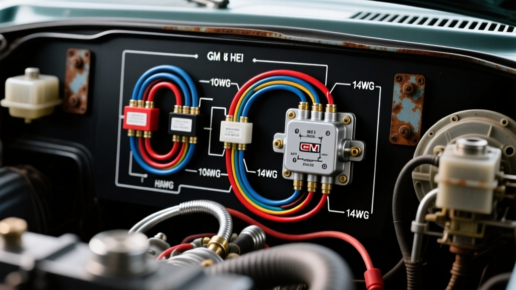
Upgrading to the Ultima GM HEI Ignition System
Swapping a legacy breaker-point distributor for an Ultima High Energy Ignition (HEI) system is one of the most reliable performance and drivability upgrades you can perform on a classic GM V8 car or truck. The Ultima HEI distributor integrates the ignition coil, magnetic pickup, and a robust 4-pin control module directly into the distributor cap, eliminating the external ballast resistor and fragile resistance wires found in 1960s and 1970s General Motors vehicles.
However, the most common cause of premature Ultima HEI module failure is not a defective part, but improper wiring. The factory ignition feed wire on classic GM vehicles was designed to carry reduced voltage to a points-style coil. Feeding an HEI module through this resistance wire starves the system of current, leading to weak spark, high-RPM misfires, and eventual thermal failure of the module. This practical installation guide details the correct Ultima ignition wiring diagram, necessary relay upgrades, and precise terminal pinouts to ensure a bulletproof ignition system.
Pre-Installation Electrical Requirements
Before routing any wires, you must verify the health of your vehicle's charging system. The Ultima HEI module requires a minimum of 11.5 volts under cranking conditions and a solid 13.8 to 14.2 volts while running. According to SAE J1128 standards for low-tension primary cables, automotive wiring must be sized to handle the specific amperage load while minimizing voltage drop over the length of the run.
The HEI system draws approximately 3 to 4 amps at idle, but peak current draw during the coil's dwell cycle can spike higher. Using the factory 18-gauge cloth-covered resistance wire will result in a severe voltage drop. To correct this, we bypass the factory wiring entirely using a dedicated 12-gauge feed wire driven by a standard Bosch-style 30A automotive relay.
Ultima HEI Cap & Module Pinout Reference
The Ultima in-cap coil HEI distributor utilizes a standardized 4-pin module configuration. Below is the definitive wiring matrix for the cap terminals and external connections.
| Terminal / Pin | Wire Color | AWG Size | Function & Connection Point |
|---|---|---|---|
| BAT (Cap Terminal) | Red | 12 AWG | Switched 12V+ Power Feed (From Relay Pin 87) |
| TACH (Cap Terminal) | White | 18 AWG | Tachometer Signal Output (To Tach Green Wire or ECU) |
| GND (Module Base) | Black | 12 AWG | Supplemental Module Ground (To Intake Manifold Bolt) |
| Relay Pin 30 | Red | 10 AWG | Constant 12V+ from Battery Positive or Starter Lug |
| Relay Pin 85 | Black | 14 AWG | Relay Coil Ground (To Engine Block or Chassis) |
| Relay Pin 86 | Yellow | 16 AWG | Relay Trigger (From Factory Ignition Switch 'IGN' Terminal) |
Step-by-Step Wiring Installation Guide
Step 1: Disable the Factory Resistance Wire
Locate the factory ignition feed wire at the firewall bulkhead connector or the ignition switch harness. On classic GM trucks and muscle cars, this is typically a pink or cloth-wrapped resistance wire. Disconnect this wire from the ignition switch and tape it back securely into the harness. Do not cut it out entirely, as you may need it for future restorations. You will use the ignition switch's 'IGN' or 'RUN' terminal merely as a low-amperage trigger signal for your new relay.
Step 2: Wire the 30A Power Relay
Mount a standard 5-pin (using only 4 pins) or 4-pin Bosch relay in the engine bay, away from extreme exhaust heat and moving linkages.
- Pin 30 (Power In): Run a 10 AWG red wire with an inline 20A MAXI fuse directly from the positive battery terminal or the starter motor main lug.
- Pin 85 (Ground): Run a 14 AWG black wire to a clean, bare-metal grounding point on the engine block or inner fender.
- Pin 86 (Trigger): Run a 16 AWG yellow wire through the firewall to the factory ignition switch 'RUN' terminal. This provides the low-amp signal to close the relay contacts.
- Pin 87 (Power Out): Run a 12 AWG red wire directly to the 'BAT' terminal on the Ultima HEI distributor cap.
Step 3: Establish a Supplemental Module Ground
While the Ultima HEI module grounds primarily through the distributor body to the engine block, aluminum intake manifolds and cast-iron block oxidation can introduce electrical resistance. As detailed in comprehensive GM HEI wiring guides by Mad Electrical, adding a supplemental ground drastically extends module life. Attach a ring terminal to one of the module's mounting screws, and route a 12 AWG black wire to a clean, tapped bolt on the intake manifold or cylinder head.
Step 4: Tachometer and EMI Suppression
Connect an 18 AWG white wire from the 'TACH' terminal on the distributor cap to your aftermarket tachometer's signal input. If you are using a modern EFI system, route this wire to the ECU's designated tach input pin. To prevent Electromagnetic Interference (EMI) from corrupting the tach signal or radio reception, ensure you are using carbon-core or spiral-wound suppression spark plug wires. Never use solid copper-core wires with an HEI system, as they will broadcast high-frequency noise that can confuse the module's magnetic pickup.
Troubleshooting Common Ultima HEI Wiring Faults
Even with a meticulous installation, electrical gremlins can occur. Use this diagnostic matrix to resolve common issues.
| Symptom | Probable Cause | Diagnostic Fix |
|---|---|---|
| No spark; engine cranks but won't start. | Blown 4-pin module due to poor grounding or reversed coil polarity. | Check supplemental ground continuity. Verify coil primary resistance (should be 0.5 - 1.5 ohms). Replace module if shorted. |
| Engine misfires severely above 3,500 RPM. | Voltage drop in the 12V feed wire; module starving for current during short dwell times. | Use a Digital Multimeter (DMM) to measure voltage at the BAT terminal while revving. If it drops below 11V, upgrade feed wire to 10 AWG or check relay contacts. |
| Tachometer needle bounces erratically. | EMI interference from solid-core plug wires or unshielded tach signal wire. | Swap to spiral-core 8mm plug wires. Route the white tach wire away from the alternator and spark plug wire looms. |
| Module overheats and fails repeatedly. | Missing dielectric grease between the module base and the distributor housing heat sink. | Remove module, clean mating surfaces with brake cleaner, and apply a generous layer of thermal dielectric grease before torquing to 18 in-lbs. |
Final Torque and Assembly Specifications
Once the wiring is verified with a multimeter and the engine fires, ensure the distributor hold-down clamp is torqued to 22 lb-ft. Over-tightening can distort the distributor housing and bind the mechanical advance weights, while under-tightening allows the distributor to rotate, altering base timing. Finally, seal all exposed crimp connections with adhesive-lined marine-grade heat shrink to prevent corrosion in the engine bay environment. By following this Ultima ignition wiring diagram and utilizing a dedicated relay feed, your GM V8 will benefit from a massive, consistent spark that maximizes combustion efficiency and throttle response.