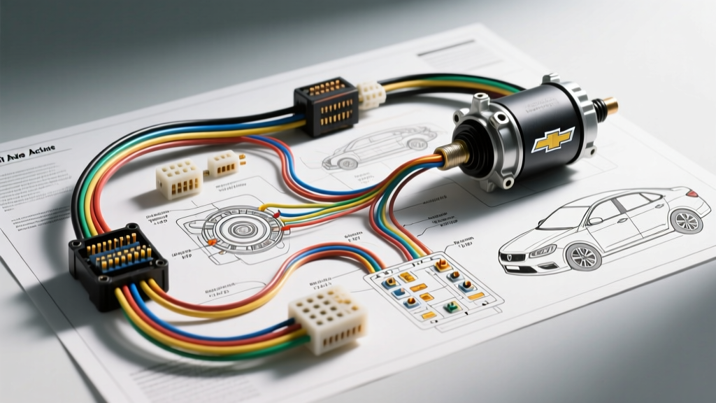
Introduction to the 4WD Front Axle Disconnect Circuit
The front axle actuator is a critical, yet highly vulnerable, component in Chevrolet and GMC 4WD systems. Whether you are diagnosing a GMT800 Silverado or a GMT900 Tahoe, interpreting the chevy front axle actuator wiring diagram is the first step toward restoring 4WD functionality. Unlike standard cabin wiring, the harness routing to the front differential is subjected to extreme thermal cycling, road salt corrosion, and physical impact from debris. This analysis breaks down the exact wiring schematics, required diagnostic tooling, and a comprehensive cost breakdown for repairing or upgrading the actuator circuit.
Decoding the Diagram: Thermal vs. Motorized Actuators
General Motors utilized two distinct front axle actuator designs across its truck and SUV platforms. Understanding which system your vehicle employs is mandatory before referencing a wiring schematic, as the pinouts, current draws, and module logic are entirely different.
GMT800 (1999–2006) 2-Pin Thermal Actuator
Early GMT800 platforms utilized a thermal-style actuator. This device contains a sealed gas chamber and a heating element. When the Transfer Case Shift Control Module (TCCM) grounds the circuit, current flows through the heater, expanding the gas to push a piston that engages the front axle collar. Due to the high resistance of the heating element, this circuit draws a steady 2.5 to 3.5 amps for several seconds during engagement.
| Pin | Wire Color | AWG (OEM) | Function | Voltage / Logic |
|---|---|---|---|---|
| A | Brown | 18 AWG | Ignition 12V+ Supply | 12V-14V (Key ON) |
| B | Light Blue | 18 AWG | TCCM Ground Control | Switched Ground |
Expert Note: The thermal actuator is notorious for slow engagement in cold weather and high current draw that melts the Delphi Packard Weather-Pack connector terminals. Many technicians perform a motorized actuator retrofit to bypass this inherent design flaw.
GMT900 (2007–2013) 4-Pin Motorized Actuator
GM transitioned to a DC motor-driven actuator for faster, more reliable engagement. The TCCM utilizes an internal H-bridge motor driver to reverse polarity, allowing the motor to both engage and disengage the front axle mechanically. This requires a 4-pin connector and distinct motor control circuits.
| Pin | Wire Color | AWG (OEM) | Function | Voltage / Logic |
|---|---|---|---|---|
| A | Brown | 16 AWG | Ignition 12V+ Supply | 12V-14V (Key ON) |
| B | Black | 16 AWG | Chassis Ground | Continuous Ground |
| C | Light Blue | 18 AWG | Motor Control 1 | PWM / Polarity Switch |
| D | Dark Green | 18 AWG | Motor Control 2 | PWM / Polarity Switch |
Tool Requirements & Diagnostic Arsenal
Diagnosing the front axle actuator circuit requires more than a basic test light. The long wire run from the TCCM (located under the driver's side dash or kick panel) to the front differential introduces significant voltage drop potential. According to AA1Car's 4WD diagnostic guidelines, verifying module logic and circuit integrity requires specialized automotive electrical tools.
| Tool / Equipment | Purpose | Estimated Cost |
|---|---|---|
| Fluke 88V Automotive Multimeter | Measuring voltage drop, resistance, and PWM signals at the TCCM. | $350 - $450 |
| GM J-35616 Back-Probe Pin Set | Safe back-probing of sealed TCCM and actuator connectors without spreading terminals. | $45 - $80 |
| Power Probe IV | Injecting 12V directly at the actuator pigtail to isolate module vs. harness failures. | $250 - $300 |
| Knipex Self-Adjusting Wire Strippers | Preventing nicked copper strands when stripping 16/18 AWG GXL wire. | $60 - $80 |
| Adhesive-Lined Heat Shrink (3M) | Environmental sealing of splice joints against differential heat and moisture. | $15 - $25 |
Cost Analysis: Repair Strategies Compared
When the wiring diagram confirms a broken circuit or severe voltage drop, technicians and DIYers must choose a repair strategy. The front axle harness is often integrated into the main chassis harness on some model years, making full OEM replacement prohibitively expensive and labor-intensive.
| Repair Strategy | Parts Cost | Labor Time | Longevity & Reliability |
|---|---|---|---|
| OEM Full Harness Replacement | $250 - $600 | 4.0 - 8.0 Hours | Excellent (Factory routing, but requires dash removal) |
| Aftermarket Pigtail Splice | $15 - $25 | 0.5 Hours | Poor (Standard PVC wire and butt connectors fail rapidly near the differential) |
| Custom GXL Wire & Metri-Pack Rebuild | $35 - $55 | 1.5 Hours | Superior (Upgraded wire gauge and sealed connectors resist heat and vibration) |
| Thermal-to-Motorized Retrofit Kit | $120 - $180 | 2.0 Hours | Excellent (Eliminates thermal delay and high-draw melting issues) |
Step-by-Step Diagnostic Decision Tree
Follow this diagnostic sequence using your multimeter and the wiring schematic to isolate the fault:
- Verify Power Supply: Back-probe Pin A (Brown wire) at the actuator connector with the ignition ON. You must read within 0.2V of battery voltage. If voltage is low, check the 4WD fuse in the underhood bussed electrical center and perform a voltage drop test on the supply wire.
- Verify Ground Integrity: For 2-pin systems, check continuity from Pin B (Light Blue) to a known good chassis ground. For 4-pin systems, verify Pin B (Black) has less than 0.1 ohms of resistance to the battery negative terminal.
- Module Logic Test: Connect a multimeter to the control pins (Light Blue/Dark Green on 4-pin systems). Command 4WD High via the dash switch. The TCCM should output a pulsed 12V signal (PWM) to the motor control pins. If the module commands voltage but the actuator does not move, the actuator motor is seized or internally open.
- Actuator Bench Test: Disconnect the harness. Apply direct 12V and Ground to the motor pins (bypassing the TCCM). If the motor spins and engages the collar, the wiring harness between the TCCM and differential is the confirmed failure point.
Expert Insights: Wire Specs & Environmental Sealing
When repairing the chevy front axle actuator wiring diagram circuit, never use standard PVC-jacketed wire (THHN or standard automotive primary wire). The proximity to the front differential exposes the harness to temperatures exceeding 250°F (121°C). As outlined in the SAE J1128 standard for Low Tension Primary Cable, you must use Cross-Linked Polyethylene (GXL or TXL) wire. GXL wire features a thinner insulation wall, allowing for easier routing through tight frame rails while maintaining a 125°C continuous temperature rating.
Furthermore, when rebuilding the connector, use a Delphi Metri-Pack 280 series with secondary terminal locks (TPA). Apply a silicone-based dielectric grease to the connector cavity to prevent moisture ingress, but never apply it directly to the terminal mating surfaces, as it can increase contact resistance and cause voltage drop on the low-amperage TCCM control circuits. By combining SAE-compliant GXL wiring, proper crimping tools, and meticulous sealing, your repair will outlast the factory OEM harness.