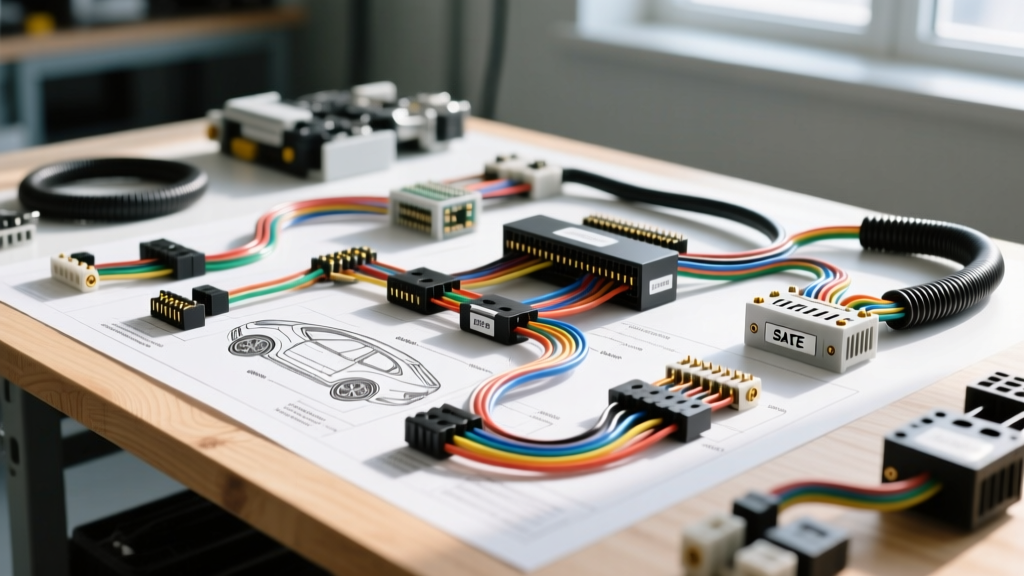
The Evolution of the Wiring Diagram Maker in Automotive Engineering
When executing complex automotive electrical projects—ranging from LS-V8 restomod conversions to full electric vehicle (EV) powertrain swaps—relying on rudimentary sketching or generic CAD tools is a recipe for catastrophic failure. Modern professional automotive electricians and harness builders utilize a specialized wiring diagram maker to engineer, validate, and document custom wiring harnesses. Unlike basic drawing software, an advanced wiring diagram maker (such as Zuken E3.series, Capital Harness, or heavily customized AutoCAD Electrical environments) operates on a netlist-based architecture. This means every wire, pin, and connector is treated as an intelligent electrical node rather than a mere graphical line.
This deep dive explores the technical methodology of using a professional wiring diagram maker to architect a custom Controller Area Network (CAN-bus) and high-current power distribution harness. We will cover SAE and DIN standardization, intelligent pinout mapping, AWG voltage-drop calculations, and formboard generation.
Standardizing Schematics: SAE and DIN Compliance
Before routing a single digital wire, the schematic library within your wiring diagram maker must be standardized. In the North American automotive aftermarket and OEM sectors, adherence to SAE International standards (specifically SAE J1292 for wiring diagrams and SAE J1939 for heavy-duty CAN networks) is critical for serviceability and safety.
Translating DIN 72552 Terminals into Digital Nodes
Many modern diagramming tools default to IEC standards, which do not align with legacy and modern automotive relay/switch terminology. A proficient harness engineer will customize their wiring diagram maker's symbol library to reflect DIN 72552 terminal designations. Configuring these standard nodes ensures that any technician reading the exported schematic instantly understands the circuit's function:
- Terminal 15: Switched ignition power (Post-start/run).
- Terminal 30: Direct battery positive (Hot at all times).
- Terminal 31: Battery negative / Chassis ground.
- Terminal 87 / 87a: Relay normally open (NO) and normally closed (NC) outputs.
By assigning these DIN tags as metadata within the wiring diagram maker, the software can automatically generate fault-finding matrices and ground distribution charts, eliminating the guesswork during physical troubleshooting.
Architecting a Custom CAN-Bus Harness
The backbone of any modern engine swap or custom Body Control Module (BCM) integration is the CAN-bus. When drafting a CAN network in a wiring diagram maker, you are not just drawing two wires; you are defining a differential signaling pair that requires strict impedance and routing parameters.
Component Selection and Pinout Mapping
For a custom BCM integration utilizing a Molex MX150 sealed connector system, the wiring diagram maker must be populated with the exact 3D cavity data. The MX150 system supports 14-22 AWG, making it ideal for sensor and CAN lines. Below is a standard 12-way MX150 BCM pinout configuration mapped within the software environment:
| Pin | Function | Wire Color (OEM Eq.) | AWG | Terminal Type |
|---|---|---|---|---|
| 1 | CAN-H (Powertrain) | Green/White | 18 AWG | MX150 Female (Tin) |
| 2 | CAN-L (Powertrain) | Blue/White | 18 AWG | MX150 Female (Tin) |
| 3 | CAN-H (Chassis) | Yellow | 18 AWG | MX150 Female (Tin) |
| 4 | CAN-L (Chassis) | Green | 18 AWG | MX150 Female (Tin) |
| 5 | Terminal 15 (Ignition) | Red/Yellow | 14 AWG | MX150 Female (Silver) |
| 6 | Terminal 30 (B+) | Red | 12 AWG | MX150 Female (Silver) |
| 7 | Terminal 31 (Ground) | Black | 12 AWG | MX150 Female (Silver) |
| 8 | 120-Ohm Term. Resistor H | N/A (Internal) | N/A | N/A |
| 9 | 120-Ohm Term. Resistor L | N/A (Internal) | N/A | N/A |
| 10 | Diagnostic Enable (K-Line) | Purple | 18 AWG | MX150 Female (Tin) |
| 11 | Sensor Ground (SGND) | Black/White | 18 AWG | MX150 Female (Tin) |
| 12 | Reserved / Shield Drain | Bare Copper | 20 AWG | MX150 Female (Tin) |
In a sophisticated wiring diagram maker, assigning the 120-ohm terminating resistors to Pins 8 and 9 ensures the software's netlist validator flags the CAN-bus as 'terminated.' If the resistance across CAN-H and CAN-L does not calculate to approximately 60 ohms (two 120-ohm resistors in parallel), the software will halt the BOM (Bill of Materials) generation, preventing a physical build that would result in severe signal reflection and ECU communication timeouts.
Wire Gauge (AWG) and Voltage Drop Calculations
One of the most powerful features of an advanced wiring diagram maker is its ability to calculate voltage drop based on wire length, material (copper vs. aluminum), and ambient temperature. This is especially critical in EV conversions where high-current traction inverters and 12V DC-DC converters share the same chassis.
Handling High-Current BMS and Inverter Lines
Consider a 400V to 12V DC-DC converter rated for 30A continuous output. Using the SAE J1292 voltage drop guidelines, a maximum 3% voltage drop is acceptable for sensitive ECU power lines. If the routing distance from the DC-DC converter to the main distribution block is 12 feet (24 feet total round-trip), the wiring diagram maker's built-in calculator dictates the minimum AWG.
Using standard copper resistivity at 20°C:
- 12 AWG: Yields a ~0.38V drop (approx 3.1% of 12V) - Borderline/Fail.
- 10 AWG: Yields a ~0.24V drop (approx 2.0% of 12V) - Pass.
The diagram maker automatically updates the BOM to specify 10 AWG cross-linked polyethylene (XLPE) wire, which is rated for 125°C, ensuring the insulation will not melt when routed near the inverter's heat sink. Furthermore, the software specifies a TE Connectivity AMPSEAL connector for the DC-DC side, as standard weatherpack connectors cannot reliably handle the thermal cycling and current density of this specific node.
Real-World Failure Modes and Digital Troubleshooting
Even with a perfect schematic, physical execution can introduce faults. A high-end wiring diagram maker allows engineers to run simulation diagnostics. For example, a common failure mode in custom LS-swaps is the ECU throwing a U0100 (Lost Communication with ECM/PCM) code. By referencing the digital schematic, a technician can immediately isolate the CAN-H and CAN-L nodes. If the diagram maker's netlist shows a missing ground reference on the terminating resistor circuit, the technician knows to check the physical splice at Pin 31 before replacing the ECU. This integration of digital logic and physical troubleshooting is what separates amateur wiring from professional automotive engineering.
From Schematic to Formboard: The Physical Translation
The final stage of the wiring diagram maker workflow is the generation of the formboard (or nail board) drawing. This 1:1 scale 2D layout dictates exactly how the harness will be taped, sleeved, and loomed on the physical assembly table.
Advanced tools allow the engineer to define breakout points, splice locations, and conduit transitions. For instance, the CAN-bus twisted pair (UTP) must remain twisted to within 2 inches of the Molex MX150 connector backshell to maintain the 120-ohm characteristic impedance and reject common-mode electromagnetic interference (EMI). The wiring diagram maker visually flags any untwisted lead lengths exceeding this tolerance on the formboard drawing.
Additionally, the software calculates the required diameter of the braided fiberglass sleeving or corrugated split-loom based on the cumulative cross-sectional area of the bundled wires. If a harness branch contains two 10 AWG power wires, four 18 AWG CAN wires, and a 16 AWG shielded sensor cable, the diagram maker calculates the exact millimeter diameter of the conduit required, factoring in a 20% fill-capacity safety margin for harness flexibility and heat dissipation.
Conclusion: Precision in Every Node
Utilizing a professional wiring diagram maker transforms automotive electrical design from a reactive, trial-and-error process into a proactive, engineered discipline. By enforcing SAE/DIN standards, validating CAN-bus termination, calculating precise AWG voltage drops, and generating accurate formboard layouts, master technicians can build custom harnesses that rival OEM reliability. Whether you are integrating a modern Coyote V8 into a classic chassis or engineering a bespoke BMS for an EV swap, the digital schematic is the undisputed blueprint for electrical success.