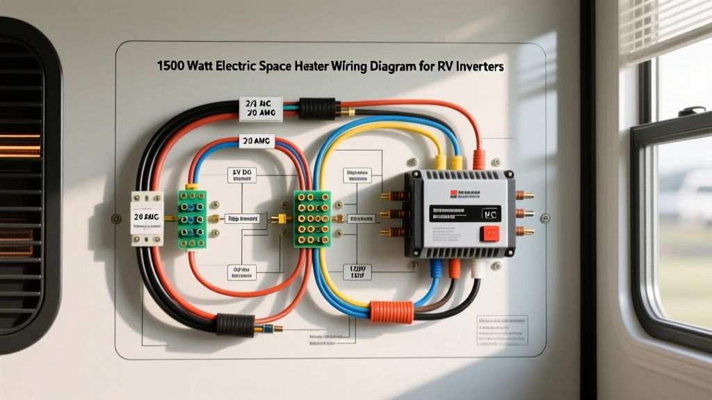
The Electrical Math: Why a 1500W Heater is a Massive Automotive Load
When transitioning from household appliances to automotive or RV electrical systems, the most common point of failure is misunderstanding the relationship between voltage, current, and wire gauge. A standard household 1500 watt electric space heater wiring diagram relies on 120V AC, drawing a manageable 12.5 amps. However, when you adapt this load for a 12V DC vehicle or camper van environment via an inverter, the physics change drastically.
Using the power formula (P = I × V), a 1500W load on a 12.0V nominal battery bank requires 125 amps. Because pure sine wave inverters operate at roughly 85% to 90% efficiency under heavy loads, your actual DC draw will spike to between 138 and 145 amps. This continuous, high-amperage draw generates significant heat and voltage drop. If you attempt to wire this using standard automotive 12V practices, you risk catastrophic thermal runaway, melted insulation, and electrical fires. This guide provides a complete, code-compliant 1500 watt electric space heater wiring diagram walkthrough specifically engineered for high-output RV and overland inverter setups.
Complete 1500 Watt Electric Space Heater Wiring Diagram Walkthrough
A safe, high-current inverter wiring schematic is divided into two distinct zones: the high-current DC side (battery to inverter) and the standard AC side (inverter to receptacle). Below is the node-by-node walkthrough of the circuit.
Node 1: The Battery Bank and BMS
A standard lead-acid or AGM battery bank will suffer severe voltage sag under a 140A continuous draw, triggering the inverter's Low Voltage Disconnect (LVD) within minutes. For a 1500W continuous load, a Lithium Iron Phosphate (LiFePO4) battery bank is mandatory. The Battery Management System (BMS) must be rated for at least 200A continuous discharge to prevent the BMS from tripping or overheating its internal MOSFETs.
Node 2: DC Overcurrent Protection (OCP)
According to the ABYC E-11 Marine and RV Electrical Standards, overcurrent protection must be placed as close to the power source as possible. For a 145A draw, a 150A or 175A Class T fuse is required. Class T fuses offer a high Ampere Interrupting Capacity (AIC) of 20,000 amps, which is critical for safely interrupting the massive short-circuit potential of a lithium battery bank. Standard ANL fuses are not recommended for lithium banks due to their lower AIC ratings.
Node 3: The DC Wiring Run
The positive and negative conductors connecting the battery busbar to the inverter must be 2/0 AWG (00 AWG) stranded, pure copper marine-grade wire. Aluminum wire or Copper Clad Aluminum (CCA) is strictly prohibited due to higher resistance and oxidation risks at high-current termination points.
Node 4: Pure Sine Wave Inverter
A 1500W heater requires a minimum 2000W pure sine wave inverter to handle the startup surge and continuous thermal load. The inverter must feature robust DC terminals capable of accepting 2/0 AWG ring terminals and an internal neutral-to-ground relay if required by your specific RV's AC panel configuration.
Node 5: AC Distribution and Receptacle
The AC output of the inverter is wired using standard 12 AWG THHN or NM-B copper wire, protected by a 20A GFCI breaker. The space heater plugs directly into this dedicated 120V AC receptacle. Under no circumstances should the 1500W heater share a 20A circuit with other high-draw appliances like a microwave or coffee maker.
Component Sizing & Specification Chart
| Component | Specification | Technical Justification |
|---|---|---|
| Inverter Size | 2000W - 3000W Pure Sine | Provides 25%+ overhead for continuous 1500W thermal loads and startup surges. |
| DC Wire Gauge | 2/0 AWG Stranded Copper | Handles 145A continuous with <3% voltage drop over a 10-foot round trip. |
| DC Fuse | 175A Class T (JLLN) | 20,000 AIC rating safely interrupts lithium short-circuits; prevents nuisance blowing. |
| DC Terminals | 3/8" Ring, 2/0 AWG, Tinned | Ensures maximum surface area contact on inverter busbars; tinning prevents corrosion. |
| AC Wire Gauge | 12 AWG Copper (THHN) | Standard NEC rating for 20A continuous AC circuits. |
| AC Breaker | 20A GFCI (Dead Front) | Protects against ground faults in damp vehicle environments. |
Step-by-Step Installation & Torque Specifications
Proper termination is just as critical as wire sizing. A loose crimp on a 140A circuit will create a high-resistance joint, generating enough heat to melt the inverter casing. Follow these installation parameters:
- Strip and Clean: Strip 5/8" of insulation from the 2/0 AWG wire. Do not nick the copper strands.
- Hex Crimp: Use a closed-barrel hex crimp tool with the correct 2/0 AWG die. The crimp should deform the copper into a hexagonal shape, creating a cold-weld bond.
- Seal: Apply 3M marine-grade adhesive-lined heat shrink over the crimp joint. Heat until the adhesive oozes from the edges to prevent moisture ingress.
- Torque DC Terminals: Connect the ring terminals to the inverter and busbar. Use a calibrated torque wrench set to 12 to 15 Nm (106 to 132 in-lbs), depending on the inverter manufacturer's specification (e.g., Victron Energy recommends 14 Nm for M8 studs).
- Torque AC Terminals: Torque the AC output terminal block screws to 1.5 to 2.0 Nm.
- Install Fuse Last: Always install the Class T fuse element only after all DC and AC connections are torqued and verified.
Alternator and DC-DC Charger Considerations
Running a 1500W space heater while driving requires careful management of the vehicle's alternator. A standard OEM alternator outputs 140A to 220A, but its internal wiring and OEM harness are not designed to route 140A to a rear auxiliary battery bank. If you wire the alternator directly to the auxiliary bank using undersized wire, the OEM harness will melt. For mobile applications, you must use a heavy-duty DC-DC charger (e.g., 60A or 100A) wired with 1/0 AWG cable directly from the starting battery's busbar, or upgrade the alternator and run a dedicated 2/0 AWG charge line with a 200A Mega fuse. For deeper architectural guidelines, refer to the Victron Energy Wiring Unlimited Guide, which details alternator-to-inverter load balancing.
Troubleshooting Voltage Drop and Thermal Runaway
Even with a correct 1500 watt electric space heater wiring diagram, environmental factors and component degradation can cause failures. Use this diagnostic tree to troubleshoot common high-load inverter issues.
Symptom: Inverter Shuts Off After 3-5 Minutes of Heater Use
- Cause 1: Voltage Sag (LVD Trigger). The battery bank's voltage is dropping below the inverter's low-voltage cutoff (typically 10.5V). Fix: Measure voltage directly at the battery terminals, then at the inverter terminals under load. If the battery reads 12.2V but the inverter reads 10.4V, you have severe voltage drop. Upgrade wire gauge or shorten the cable run.
- Cause 2: BMS Thermal Protection. The battery's BMS is overheating and disconnecting. Fix: Verify the BMS continuous discharge rating. If it is a 100A BMS, it will trip under a 140A load. Upgrade to a 200A BMS or parallel a second identical battery bank.
Symptom: DC Terminals or Fuse Holder are Hot to the Touch
- Cause 1: Insufficient Torque. Vibration from the vehicle has loosened the M8 or M10 nuts on the busbar. Fix: Power down, disconnect, clean the contact surfaces with contact cleaner, and re-torque to 14 Nm.
- Cause 2: CCA Wire Fraud. The wire used is Copper Clad Aluminum, which has higher resistance and creeps under torque. Fix: Cut a strand and scrape it. If it is silver underneath, replace the entire run with pure marine-grade copper.
Symptom: GFCI Breaker Trips Immediately Upon Plugging In Heater
- Cause: Neutral-Ground Bonding Conflict. Many inverters feature an internal neutral-to-ground relay. If your RV's main AC panel already has a neutral-ground bond, the GFCI will detect a fault. Fix: Consult the NFPA 70 National Electrical Code (Article 551) regarding RV grounding schemes. Ensure only one neutral-ground bond exists in the AC system, typically at the main transfer switch or inverter, and disable the inverter's internal bond if wiring to a sub-panel.
Final Safety Verification
Before operating the space heater, conduct a full-load thermal scan. Turn the heater on to its maximum 1500W setting. Using an infrared thermal camera or laser thermometer, scan the Class T fuse holder, the DC busbar connections, and the inverter DC terminals after 15 minutes of continuous operation. No termination point should exceed ambient temperature by more than 30°C (54°F). If any point is significantly hotter, power down immediately and inspect the crimp and torque of that specific joint.