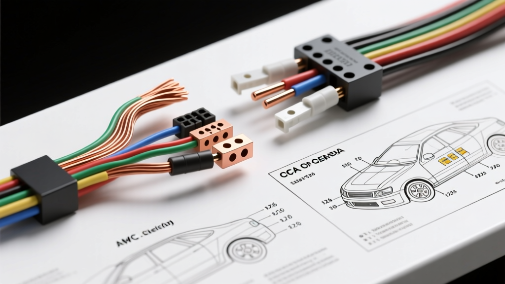
Decoding Amplifier Wiring Diagrams Car Audio: A Selection Guide
When upgrading a vehicle's sound system, interpreting amplifier wiring diagrams car audio schematics is only half the battle; selecting the correct physical wiring kit to execute those diagrams is where most installations fail. A wiring diagram provides the logical roadmap for power, ground, and signal routing, but the metallurgical quality and American Wire Gauge (AWG) accuracy of the kit you purchase dictate the electrical efficiency and longevity of the system. This guide compares premium Oxygen-Free Copper (OFC) and budget Copper-Clad Aluminum (CCA) wiring kits, breaking down the exact specifications, routing diagrams, and OEM integration pinouts required for high-current mobile audio environments.
Product Comparison: OFC vs. CCA Amplifier Wiring Kits
The most critical decision when purchasing a wiring kit for your amplifier diagram is the conductor material. The mobile electronics industry is flooded with CCA wire disguised as pure copper. According to the SAE International J1128 standard for low-tension primary automotive cable, true OFC wire contains 99.9% pure copper, offering superior conductivity and corrosion resistance. CCA wire features an aluminum core with a thin copper electroplated coating. Aluminum has roughly 61% the conductivity of copper, meaning a 4 AWG CCA wire performs electrically closer to a 6 AWG or 8 AWG OFC wire, leading to severe voltage drop under heavy bass transients.
Specification Chart: 4 AWG OFC vs. 4 AWG CCA
| Specification | True 4 AWG OFC Kit | 4 AWG CCA (Budget) Kit |
|---|---|---|
| Conductor Material | 99.9% Oxygen-Free Copper | Aluminum Core / Copper Clad |
| Strand Count (Typical) | 2,100+ Fine Strands | 800 - 1,200 Thick Strands |
| Max Continuous Current | 150 Amps | 95 Amps |
| Resistance (per 1,000 ft) | 0.248 Ohms | 0.410 Ohms |
| Corrosion Risk at Crimps | Very Low | High (Galvanic Oxidation) |
| Best Application | 1000W+ Class D / Class AB Amps | Sub-300W Entry-Level Amps |
Anatomy of the Power Circuit Diagram
Every standard amplifier wiring diagram car audio layout relies on three primary legs: the 12V+ positive feed, the chassis ground, and the remote turn-on trigger. When executing the power leg, wire gauge selection must match the total current draw of all amplifiers connected to the distribution block.
Main Power Routing and Fuse Selection
For a standard 5-channel system drawing up to 120A, a 4 AWG OFC power wire is mandatory. The diagram must show the main fuse placed within 18 inches of the vehicle's positive battery terminal. This is a strict requirement outlined by the Consumer Technology Association (CTA-2015) mobile electronics installation standards.
- ANL Fuses: Recommended for high-current applications (80A to 250A). They feature a flat blade design that provides a massive surface area for contact, minimizing resistance and heat buildup compared to cylindrical fuses.
- AGU Fuses: Glass cylinder fuses suitable only for low-current setups (under 60A). The crimp-on end caps often introduce micro-resistances that can melt under sustained high-SPL bass loads.
When terminating the power wire at the battery, use a 3/8-inch closed-loop ring terminal, crimped with a hex-compression tool and sealed with adhesive-lined marine heat shrink to prevent battery acid off-gassing from corroding the copper strands.
Grounding Architecture
The ground circuit completes the electrical loop and is the most common source of noise in car audio. The wiring diagram should dictate a ground wire length of no more than 36 inches, ideally under 18 inches. You must scrape the chassis down to bare, unpainted metal. Use a brass wire brush attached to a drill to remove the factory E-coat and primer. Secure the 4 AWG ground ring terminal using a factory M8 or M10 structural bolt, applying a torque of 15-20 ft-lbs. Never ground to a seatbelt anchor or a thin sheet-metal bracket, as these cannot handle high-amperage transient return currents.
Signal Routing: RCA vs. High-Level Integration Diagrams
Modern vehicle architectures heavily influence the signal portion of your amplifier wiring diagram. If you are retaining the factory OEM head unit, you must choose between tapping the high-level speaker wires or utilizing a Digital Signal Processor (DSP) with fiber-optic integration.
Standard Aftermarket Harness Pinout (Low-Level RCA)
When using an aftermarket double-DIN receiver, the diagram utilizes shielded RCA cables for the audio signal and a dedicated 18 AWG blue/white striped wire for the remote turn-on trigger. Below is the standard EIA/CTA color code pinout for the head unit harness:
| Wire Color | Function | Connection Point |
|---|---|---|
| Yellow (12 AWG) | Constant 12V+ (Memory) | Battery or Always-On Fuse Tap |
| Red (12 AWG) | Switched 12V+ (Accessory) | Ignition Fuse Tap |
| Black (12 AWG) | Chassis Ground | Metal Dash Support Bracket |
| Blue w/ White Stripe | Amplifier Remote Turn-On | Amp REM Terminal (Max 2A draw) |
| Shielded RCA (White/Red) | Front Pre-Out Signal | Amp Input CH 1/2 |
| Shielded RCA (Gray/Green) | Rear/Sub Pre-Out Signal | Amp Input CH 3/4 |
Premium OEM System Integration (High-Level to LOC)
In vehicles equipped with premium amplified systems (e.g., Bose, Fender, Harman Kardon), the factory amplifier outputs a crossed-over, equalized, high-level signal. Your wiring diagram must incorporate a Line Output Converter (LOC) or an active DSP.
When tapping high-level wires, use T-taps or, preferably, strip and solder the connections. A common failure mode in these diagrams is routing the high-level speaker wires parallel to the 12V+ power wire. This induces electromagnetic interference (EMI), resulting in severe alternator whine. Always route signal wires down the center console or passenger side, and power wires down the driver side rocker panel.
Troubleshooting Common Wiring Diagram Failures
Even with a perfect schematic, physical installation variables can cause system failures. Use a digital multimeter (DMM) to diagnose these common issues:
Voltage Drop and Amplifier Protect Mode
If your amplifier's thermal or voltage protection LED engages during heavy bass hits, you are experiencing voltage drop. Set your DMM to DC Voltage. Place the red probe on the amplifier's positive terminal and the black probe on the amplifier's ground terminal. Play a 40Hz test tone at 75% volume.
- Acceptable Reading: 12.8V to 14.4V
- Warning Zone: 11.5V to 12.5V (Indicates undersized wiring or weak alternator)
- Protect Mode Trigger: Below 10.5V (Immediate shutdown)
If the voltage drops below 11.5V, re-evaluate your wiring kit. Upgrading from CCA to OFC, or stepping up from 4 AWG to 1/0 AWG, will reduce resistance and stabilize the voltage rail. For comprehensive installation methodologies and vehicle-specific routing guides, the Crutchfield Amplifier Installation Guide remains an excellent supplementary resource for verifying chassis-specific firewall grommets and battery terminal adapters.
Ground Loop Isolation
If you hear a high-pitched whine that rises and falls with engine RPM, you have a ground loop. This occurs when the head unit and the amplifier are grounded at different electrical potentials. Verify that the RCA shields are not shorting against the chassis. If the OEM charging system is outputting dirty DC ripple current, installing a 1:1 ground loop isolator on the RCA lines or upgrading the vehicle's 'Big Three' wiring (Alternator to Battery, Battery to Chassis, Engine Block to Chassis) using 1/0 AWG OFC wire will stabilize the electrical reference ground and eliminate the noise.