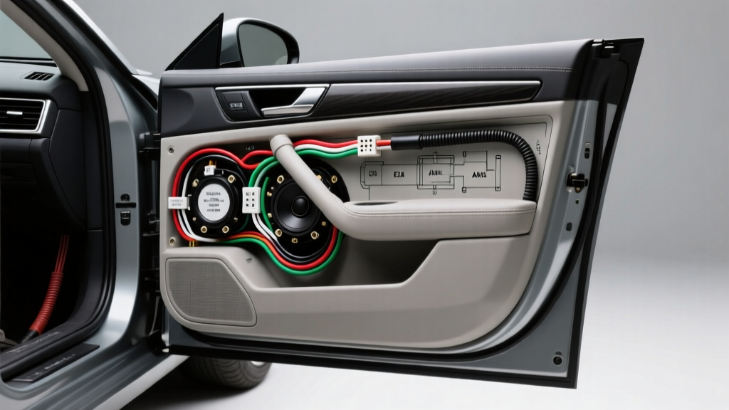
Introduction to Automotive Audio Wiring Fundamentals
Upgrading your vehicle's audio system is one of the most rewarding DIY automotive projects you can undertake. However, the success of your installation hinges entirely on your ability to interpret a car speaker wiring diagram. Unlike household electrical systems, automotive audio relies on a 12-volt DC environment, specific impedance matching, and standardized color codes to ensure acoustic phase alignment and electrical safety.
For beginners, staring at a mess of copper behind a dashboard can be intimidating. This guide breaks down the fundamentals of reading wiring schematics, understanding wire gauge requirements, and tracing signals from the head unit to the door panels. Whether you are replacing blown factory paper cones or installing an aftermarket amplifier, mastering these basics will prevent short circuits, blown channels, and acoustic phase cancellation.
Decoding the Standard Car Speaker Wiring Diagram
The aftermarket car audio industry relies on the EIA/CEA (Electronic Industries Alliance / Consumer Electronics Association) color code standard, specifically CEA-2015. When you look at a universal wiring harness diagram, you will notice a consistent color scheme designed to make channel identification foolproof. The standard utilizes a solid color for the positive (+) terminal and a matching color with a black stripe (or tracer) for the negative (-) terminal.
EIA/CEA Standard Speaker Wire Color Codes
| Speaker Location | Positive (+) Wire | Negative (-) Wire | Common Impedance |
|---|---|---|---|
| Front Left | White | White with Black Stripe | 4 Ohms |
| Front Right | Gray | Gray with Black Stripe | 4 Ohms |
| Rear Left | Green | Green with Black Stripe | 4 Ohms |
| Rear Right | Purple | Purple with Black Stripe | 4 Ohms |
| Subwoofer (Mono) | Blue | Blue with Black Stripe | 2 or 4 Ohms |
Note: Factory OEM wiring diagrams rarely follow these aftermarket standards. For example, a Ford vehicle might use Violet/Orange and Violet/Brown for the right rear speaker. Always use a digital multimeter (DMM) or a dedicated wire testing tool to verify factory harness pins before splicing.
Wire Gauge (AWG) and Material Specifications
A critical mistake beginners make is using wire that is too thin for the distance and power requirements of their speakers. Automotive wire is measured in American Wire Gauge (AWG). A lower AWG number indicates a thicker wire with lower electrical resistance. Using undersized wire results in voltage drop, which robs your speakers of dynamic range and can cause your head unit's internal amplifier to overheat and enter thermal protection mode.
AWG Sizing Chart for Speaker Runs
| Wire Gauge (AWG) | Max Power (RMS) | Max Run Length | Recommended Application |
|---|---|---|---|
| 18 AWG | 25 Watts | 8 Feet | Small dash speakers, tweeters |
| 16 AWG | 50 Watts | 15 Feet | Standard 6.5' door speakers (Head unit power) |
| 14 AWG | 100 Watts | 20 Feet | Component speakers, amplified mid-bass |
| 12 AWG | 200+ Watts | 25+ Feet | High-power woofers, subwoofer enclosures |
OFC vs. CCA: The Material Debate
When purchasing speaker wire, you will encounter two main materials: Oxygen-Free Copper (OFC) and Copper-Clad Aluminum (CCA). According to SAE J1128 standards for automotive primary cable, pure copper is the benchmark for conductivity. CCA wire is cheaper but has roughly 40% higher electrical resistance than OFC. Furthermore, CCA is brittle; when routed through a car door hinge, the aluminum core is highly susceptible to work-hardening and snapping over time. Always invest in stranded OFC wire with a silicone or PVC jacket for automotive applications.
Routing and the Door Boot Vulnerability
When tracing a car speaker wiring diagram from the dashboard to the front doors, the signal must pass through the vehicle's A-pillar and into the door via a flexible rubber tube known as the door boot or flex conduit. This is the most common failure point in automotive audio wiring.
Every time you open and close your car door, the wires inside this boot bend and flex. Over years of use, the copper strands can fatigue and break, leading to intermittent audio dropouts or complete channel failure. When running new 16 AWG OFC wire through a door boot:
- Use a fish tape or stiff wire hanger to pull the new cable through the rubber grommet.
- Leave a 'service loop' (a small amount of slack) on both sides of the boot to reduce tension when the door is fully opened.
- Apply dielectric grease to the connector pins inside the door cavity to prevent corrosion from water ingress.
Factory vs. Aftermarket Harness Pinouts
To avoid cutting your vehicle's factory wiring, you should always use a vehicle-specific wiring harness adapter. These adapters plug directly into the OEM radio connector and feature bare, color-coded wires that match the CEA-2015 aftermarket standard mentioned above.
For example, if you are installing an aftermarket receiver in a late-model GM vehicle, you might use a Metra or Axxess harness. The factory Bose or premium amplified systems often use balanced differential audio signals rather than standard single-ended ground-referenced signals. In these cases, a standard wiring diagram will not suffice; you will need a Line Output Converter (LOC) or a specialized integration module (like a PAC AudioPro) to sum the factory signals and convert them to a standard pre-amp level RCA output.
Troubleshooting: Acoustic Phase and the 9V Trick
A properly wired car audio system requires all speakers to be 'in phase.' This means that when the amplifier sends a positive voltage pulse, all speaker cones push outward simultaneously. If you accidentally swap the positive and negative wires on your left front door speaker, that cone will pull inward while the others push outward. This creates an acoustic short circuit, resulting in a severe loss of bass response and a hollow, disjointed soundstage.
How to Test Speaker Phase Before Installation
Before mounting your new speakers into the door baffle, you can easily verify your wiring using a standard 9-volt battery:
- Strip the ends of your speaker wire and connect them to your head unit or amplifier channel.
- Turn the volume to zero and power on the unit to ensure the amplifier is active.
- Alternatively, for unamplified testing, take a standard 9V battery.
- Briefly touch the positive (+) speaker wire to the positive terminal of the battery, and the negative (-) wire to the negative terminal.
- Observe the speaker cone: If the cone pushes outward toward you, your polarity is correct. If it sucks inward, your wires are reversed.
Safety Note: Never hold the 9V battery to the wires for more than a second. Prolonged contact will send a continuous DC current through the voice coil, causing it to overheat and melt the internal copper windings.
Final Integration and Continuity Testing
Once all connections are soldered and sealed with heat-shrink tubing (avoid electrical tape, as the adhesive melts in high-temperature car interiors), use a Digital Multimeter (DMM) set to the continuity or resistance (Ohms) setting. Disconnect the speaker from the amplifier, place the DMM probes on the amplifier's speaker terminals, and verify you read approximately 4.0 ohms. A reading of 'OL' (Open Loop) indicates a broken wire between the dash and the door, while a reading of '0.00' indicates a dead short that will immediately blow your head unit's internal fuse or trigger the amplifier's protection mode.
For comprehensive vehicle-specific pinouts and factory connector diagrams, resources like Crutchfield's Vehicle Fit Database and the DIYMobileAudio community forums remain invaluable references for both beginners and seasoned installers. Taking the time to understand your car speaker wiring diagram before making a single cut will ensure a clean, reliable, and audiophile-grade installation.