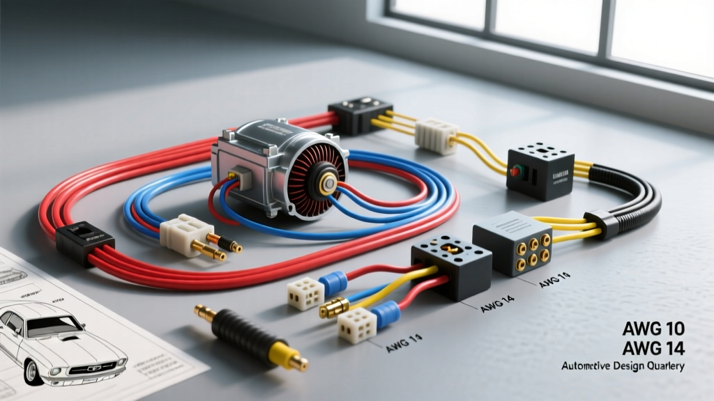
The Limits of the Factory 1968 Mustang Electrical System
When Ford engineers drafted the original 1968 Mustang wiring diagram, the electrical demands of the vehicle were remarkably modest. A stock 289 or 302 V8 equipped with an AM radio, heater blower, and incandescent lighting rarely exceeded a continuous draw of 40 amps. The factory Autolite 1G alternator, typically rated between 38 and 55 amps, was perfectly adequate for this load. However, modern upgrade and modification projects completely shatter these original parameters.
Today's classic Mustang builds frequently feature electronic fuel injection (EFI) systems like the Holley Sniper or FiTech, dual high-draw electric cooling fans, MSD capacitive discharge ignitions, and high-output fuel pumps. An EFI system alone can draw 20+ amps under load, while a pair of 16-inch electric fans can pull 25 to 30 amps combined. When you factor in modern LED conversion relays, electric water pumps, and digital instrument clusters, the total continuous amperage draw easily surpasses 90 amps. Relying on the factory 50-year-old copper harness and the original ammeter loop is a guaranteed recipe for melted insulation, voltage drop, and catastrophic electrical fires.
Decoding the Factory 1968 Mustang Wiring Diagram
To safely modify a first-generation Mustang, you must first understand the architecture of the factory main harness. The 1968 model year utilized a true series ammeter, meaning the entire charging current generated by the alternator flowed directly through the gauge on the instrument cluster before reaching the battery.
Bypassing the Factory Ammeter Shunt
In the factory 1968 Mustang wiring diagram, the main charge wire (typically a heavy Yellow 10 AWG wire) routes from the alternator output stud to the back of the ammeter. A corresponding Black/Yellow wire exits the ammeter and routes down to the battery side of the starter solenoid. When you upgrade to a 100-amp or 140-amp alternator, pushing that volume of current through the factory ammeter posts and 10 AWG wire will generate excessive heat, eventually melting the instrument cluster housing.
The Fix: You must bypass the ammeter. Disconnect the battery and remove the instrument cluster. Locate the Yellow and Black/Yellow wires on the ammeter studs. Remove them, crimp them together using a heavy-duty adhesive-lined heat shrink butt connector (or solder and seal them), and tuck the connection safely behind the dash. This permanently completes the factory circuit without sending high current through the gauge. You will then need to install an aftermarket voltmeter to monitor system health.
Upgrade Project 1: High-Output Alternator Conversion
Swapping the weak Autolite 1G for a modern high-output alternator (such as a Powermaster 1-wire or a Delco 12SI/CS130 conversion) is the most critical upgrade for a modified Mustang. However, the wiring requirements change drastically.
Autolite 1G to 1-Wire Alternator Pinout Changes
The factory Autolite 1G plug features two spade terminals: STA (Stator) and FLD (Field). The FLD terminal receives 12V from the ignition switch via a resistance wire (Red/Green stripe) to excite the alternator. The STA terminal pulses the factory idiot light or regulates the internal voltage.
When converting to a high-output 1-wire alternator, the internal voltage regulator handles the excitation automatically once the engine reaches a specific RPM threshold (usually around 1,200 RPM). You must cap off and secure the factory STA and FLD wiring plugs to prevent them from shorting against the engine block. Warning: Never leave the factory FLD wire connected to a 1-wire alternator case, as it will backfeed 12V into the ignition circuit, causing the engine to run-on after you turn the key off.
Routing the Main Charge Wire
Because the factory ammeter is bypassed and the original harness cannot handle the amperage, you must run a dedicated main charge wire. According to SAE J1128 standards for low-tension primary cable, wire gauge must be sized based on amperage and length to prevent voltage drop.
- Alternator Output to Starter Solenoid: Use 4 AWG stranded copper wire for alternators rated up to 140 amps. If your run exceeds 6 feet, step up to 2 AWG.
- Overcurrent Protection: Install a 150A ANL fuse or Mega Fuse within 18 inches of the starter solenoid connection. This protects the main charge wire in the event of a dead short against the chassis.
- Terminations: Use heavy-duty, adhesive-lined ring terminals. Apply dielectric grease to the alternator B+ post and the starter solenoid battery post to prevent galvanic corrosion.
Upgrade Project 2: Engine Bay Relay Panel Integration
Running high-draw accessories like electric fans and fuel pumps directly through the factory headlight or ignition switches will melt the switch contacts. The factory 1968 Mustang wiring diagram was never designed to carry 30 amps through the dash. The solution is installing a centralized, fused relay panel in the engine bay, using the factory switches only as low-amperage 'triggers'.
Standard ISO Relay Pinout Reference
When wiring your custom relay panel, you will utilize standard 5-pin ISO automotive relays. Below is the definitive pinout configuration you must follow to ensure proper circuit isolation and safety.
| Pin Number | Terminal Type | Function & Wire Gauge Recommendation |
|---|---|---|
| 30 | Common (Power In) | Constant 12V from the battery/fuse block. Use 10 AWG for fans/pumps, 12 AWG for lights. |
| 87 | Normally Open (Power Out) | Switched 12V output to the accessory (e.g., fuel pump positive). Match gauge to Pin 30. |
| 85 | Coil Ground | Ground trigger for the relay coil. Use 14 AWG wire to a clean chassis ground. |
| 86 | Coil Power (Trigger) | 12V trigger from the factory dash switch (e.g., heater switch for fan trigger). Use 16 AWG. |
| 87a | Normally Closed | Unused in most high-draw accessory upgrades. Insulate and secure to prevent shorts. |
The Ignition Switch 'I' Terminal Trap
A notorious mistake made during EFI and HEI ignition upgrades on the 1968 Mustang involves the ignition switch's 'I' (Ignition) terminal. In the factory diagram, the 'I' terminal provides a full 12V to the coil only while the key is held in the 'Start' position, bypassing the factory Pink resistance wire. Once the key returns to the 'Run' position, the 'I' terminal drops to 0V, and the coil runs on the reduced voltage from the resistance wire.
If you wire your EFI main relay trigger or your MSD ignition box's 12V switched source to the 'I' terminal, the system will fire up while cranking, but will instantly die the moment you release the key to the 'Run' position. Always use a multimeter to verify that your chosen trigger wire maintains 12V in both the 'Run' and 'Start' key positions. The factory 'ACC' terminal or a dedicated fused tap off the 'Run' side of the ignition switch are the correct sources.
Upgrading the Chassis and Engine Grounds
The most overlooked aspect of any classic Mustang modification project is the return path to the battery. The factory 1968 Mustang wiring diagram relies heavily on the engine block and chassis body panels to complete circuits. Over decades, rust, polyurethane paint, and powder coating act as insulators, creating massive resistance.
When upgrading your alternator and adding relays, you must upgrade your ground straps. Replace the factory braided engine-to-firewall strap with a 2 AWG braided copper ground strap. This ensures that the engine block, cylinder heads, and intake manifold have a zero-resistance path back to the battery negative terminal. This single upgrade will cure erratic factory gauge behavior, slow wiper motors, and weak spark issues that many builders mistakenly blame on the alternator or ignition system. For further reading on classic Ford charging system diagnostics and ground path theory, Madelectrical's technical archives provide exceptional foundational knowledge.
Authoritative References
- 1968 Ford Mustang Official Shop Manual (Wiring & Electrical Section) - Osborne Manuals.
- SAE J1128: Low Tension Primary Cable Standard - Society of Automotive Engineers.
- Classic Car Charging Systems and Wiring Theory - Madelectrical Technical Resources.