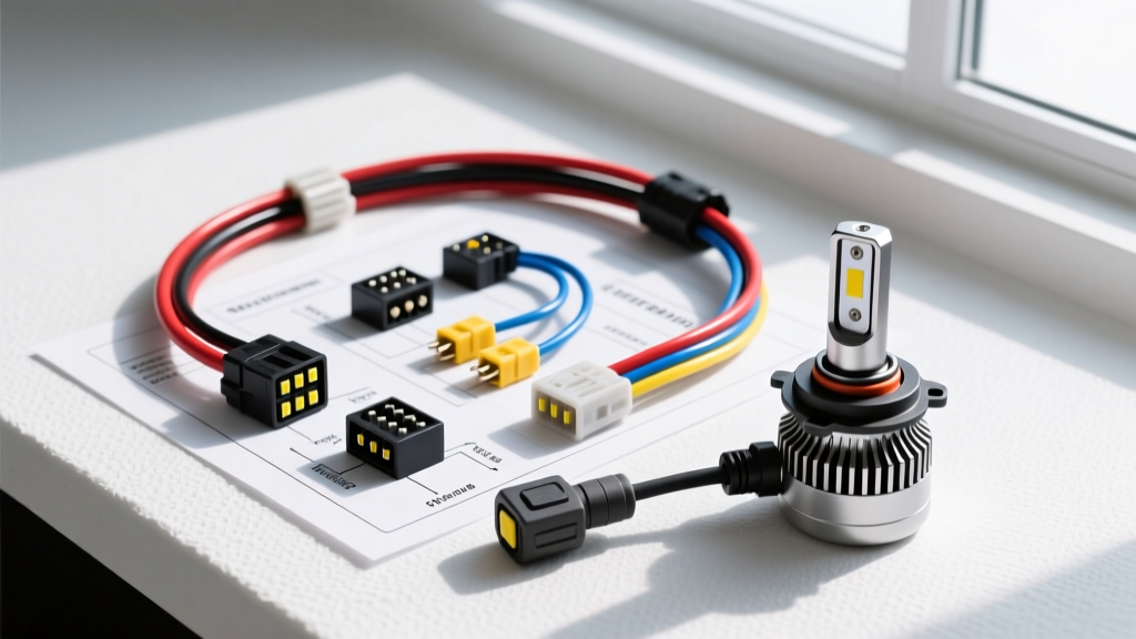
Why Direct-Tapping Fails: The Case for a Relay Harness
Upgrading from factory halogen bulbs to high-output LED fog lights, or adding auxiliary fog lamps to a vehicle that lacked them, requires a thorough understanding of the circuit's limitations. A common mistake during these modification projects is direct-tapping the new lights into the existing headlight switch or Body Control Module (BCM) output. Factory headlight switches and OEM BCM high-side drivers are engineered to handle specific amperage loads—typically around 4.5 amps for a standard 55W H11 halogen bulb. They are not designed to manage the high inrush currents of some aftermarket LED drivers, nor are they optimized for the low-draw characteristics of modern LEDs.
Direct-tapping an auxiliary fog light wiring diagram without a relay often results in melted OEM switch contacts, severe voltage drop, or immediate BCM protection shutdowns. To execute a professional-grade upgrade, you must isolate the high-current load from the low-current trigger circuit using a standard ISO 4-pin relay. This guide details the exact H11 LED fog light wiring diagram, wire gauge specifications, and BCM integration strategies required for a reliable, dealership-quality modification.
Anatomy of the H11 Fog Light Wiring Diagram
The core of this modification project relies on the Bosch-style ISO mini relay. This electromechanical switch allows a low-amperage signal from your vehicle's OEM steering column stalk or BCM to safely activate a high-amperage circuit drawing directly from the battery. Understanding the pinout is critical before cutting or crimping any wire.
- Pin 30 (Common): Receives constant 12V+ power directly from the battery positive terminal, protected by an inline fuse.
- Pin 87 (Normally Open - NO): The load output. This connects to the positive terminal of your H11 LED fog light driver.
- Pin 86 (Coil Positive): The trigger input. This connects to the OEM fog light switch output or BCM trigger wire.
- Pin 85 (Coil Negative): The ground for the internal electromagnet coil. This must be secured to a clean, unpainted chassis ground point.
When the OEM switch is activated, 12V travels to Pin 86, energizing the coil. The resulting magnetic field pulls the internal contactor, bridging Pin 30 to Pin 87 and delivering full battery voltage to the fog lights with minimal voltage drop.
Bill of Materials & Wire Gauge Specifications
Adhering to SAE J1128 Low Voltage Cable Standards is mandatory for engine bay routing. Standard PVC wire will melt or become brittle near the radiator or exhaust manifolds. Always use TXL (Thin-wall cross-linked) or GXL wire, rated for 125°C continuous operation.
| Component / Circuit | Specification | Purpose & Routing Notes |
|---|---|---|
| Power Feed (Pin 30) | 12 AWG TXL, Red | Battery positive to relay. Must handle up to 15A continuous. |
| Load Output (Pin 87) | 12 AWG TXL, Blue | Relay to H11 LED positive driver input. |
| Trigger Signal (Pin 86) | 16 AWG TXL, Green | BCM/Stalk switch to relay coil. Low current (<1A). |
| Relay Ground (Pin 85) | 16 AWG TXL, Black | Relay coil to chassis ground ring terminal. |
| Primary Protection | 15A ATO/ATC Inline Fuse | Installed within 6 inches of the battery terminal on Pin 30 wire. |
| H11 Connector | PGJ19-1 Base Housing | PPS-GF30 high-temp housing with silver-plated 2.8mm female terminals. |
Step-by-Step Relay Harness Integration
1. Battery and Power Routing
Begin by disconnecting the negative battery terminal. Measure and cut the 12 AWG red TXL wire for Pin 30. Crimp a ring terminal on one end and secure it to the battery positive post. Do not solder this connection; solder can wick under the insulation and create a rigid point that fractures under engine vibration. Use a heavy-duty open-barrel crimp tool. Slide a piece of adhesive-lined polyolefin heat shrink over the crimp and apply heat until the sealant extrudes from the edges. Route the wire along the factory wiring loom, avoiding the exhaust headers and steering shaft, terminating at the relay location in the engine bay.
2. Load Side Termination
Wire Pin 87 using the 12 AWG blue TXL wire. At the fog light end, you will interface with the H11 connector. The H11 bulb uses a PGJ19-1 base. If you are splicing into an existing OEM H11 harness, use a T-tap only for testing; for a permanent modification, cut the OEM wire and use a heat-shrink butt splice to connect your 12 AWG load wire to the factory harness leading to the bulb socket. Ensure the ground wire for the fog light itself is securely bolted to the chassis, as poor grounding is the leading cause of premature LED driver failure.
3. Grounding the Coil
Pin 85 requires a solid chassis ground. Locate a factory grounding bolt on the fender well or firewall. Remove the bolt, clean the metal surface with sandpaper to remove e-coat and paint, and attach a 16 AWG black wire with a star-washer ring terminal to ensure a bite into the bare metal. Re-torque the bolt to the manufacturer's specification (typically 8-10 Nm for M6 grounding bolts).
OEM Steering Column Stalk & BCM Integration
The most complex part of any fog light wiring diagram upgrade is sourcing the trigger signal for Pin 86. On modern vehicles (2015 and newer), the steering column stalk does not carry the actual load current. Instead, it sends a multiplexed LIN-bus or low-voltage signal to the BCM, which then outputs a trigger wire to the factory fog light relay or bulb.
Locating the Trigger: Use a digital multimeter (DMM) to back-probe the BCM connector or the factory fog light harness at the bumper. With the ignition ON and the factory fog light switch engaged, you should see a 12V reference on the trigger wire. If the vehicle uses a low-side switch (switch to ground), you will need to wire Pin 86 to a switched 12V ignition source (like the fuel pump relay or ignition coil fuse tap) and route Pin 85 to the OEM switch trigger wire. Always consult a vehicle-specific service manual or resources like Hella Tech World Lighting Systems to verify the switching topology (high-side vs. low-side) before making connections.
Troubleshooting CANbus and PWM Flicker Issues
When upgrading to LED fog lights, the most common failure mode is not a wiring fault, but a software-level rejection by the vehicle's CANbus system. Factory BCMs monitor circuit current draw to detect blown bulbs (Open Load Detection). A standard H11 halogen draws 4.5A. An H11 LED typically draws between 1.2A and 2.5A. The BCM interprets this low draw as a blown bulb, triggering a dashboard warning light and often utilizing Pulse Width Modulation (PWM) to rapidly cycle the power on and off to 'test' the circuit, resulting in severe LED flickering.
The Fix: Active Decoders vs. Load Resistors
To resolve this, your fog light wiring diagram must incorporate a CANbus decoder. While traditional 50W 6-ohm ceramic load resistors can trick the BCM by generating artificial heat to simulate a halogen draw, they defeat the efficiency purpose of LEDs and create a severe fire hazard if mounted near plastic bumper covers. Instead, install an active solid-state CANbus decoder module in parallel with the H11 LED driver. These modules store capacitance and communicate with the BCM's high-side switch, providing the exact inrush current signature the BCM expects without generating excessive thermal waste.
Final Validation: Voltage Drop Testing
Before reassembling the bumper covers and finalizing the project, perform a voltage drop test to validate the integrity of your wiring. Reconnect the battery and turn on the fog lights. Set your DMM to DC Volts. Place the red probe on the battery positive terminal and the black probe on the Pin 87 load wire right at the H11 connector. A reading above 0.2V indicates excessive resistance in the power feed (usually a bad crimp or undersized wire). Next, test the ground side by placing the red probe on the H11 ground wire and the black probe on the battery negative terminal. Again, the drop must be under 0.2V. By strictly following this relay-based fog light wiring diagram and validating with a DMM, you ensure maximum lumen output and long-term reliability of your LED lighting upgrade.
For further reading on automotive terminal retention and crimping standards, refer to the TE Connectivity Automotive Terminals engineering guides to ensure your harness survives the harsh under-hood environment.