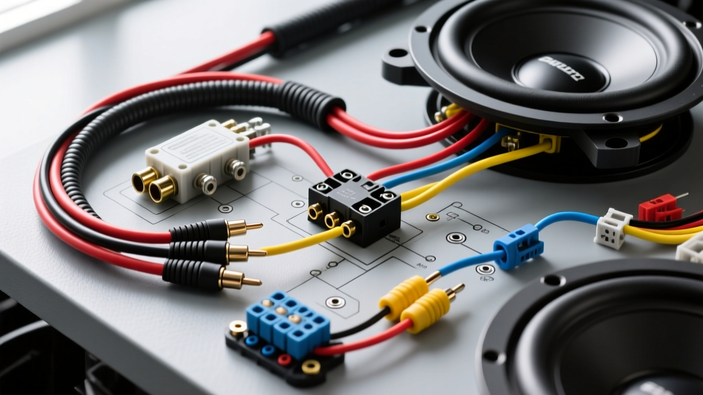
Introduction to the Audio Upgrade Project
Upgrading your vehicle's audio system with a dedicated subwoofer and amplifier requires more than just running a few wires. A precise wiring diagram for subwoofer and amp configurations is critical to ensure optimal sound quality, electrical safety, and long-term reliability. Whether you are installing a 500W RMS Class-D monoblock or a multi-channel amplifier, understanding the interplay between power delivery, signal routing, and remote triggering is the hallmark of a professional installation.
In this comprehensive guide, we break down the exact wiring schematics, wire gauge requirements, and routing protocols necessary to complete a high-fidelity aftermarket bass upgrade. We will cover everything from calculating amperage draw to integrating Line Output Converters (LOCs) with factory head units, ensuring your modification project meets Mobile Electronics Certified Professional (MECP) standards.
The Core Wiring Diagram for Subwoofer and Amp
A complete subwoofer and amplifier circuit consists of three primary sub-systems: the high-current power and ground circuit, the low-voltage audio signal path, and the remote turn-on trigger. Visualizing the wiring diagram for subwoofer and amp setups requires separating these circuits to prevent Electromagnetic Interference (EMI) and ground loops.
1. High-Current Power and Ground Circuit
The power circuit is responsible for delivering stable voltage from the vehicle's battery to the amplifier's B+ terminal. For a standard 500W to 800W RMS subwoofer amplifier, 4 AWG (American Wire Gauge) Oxygen-Free Copper (OFC) is the industry standard. Avoid Copper-Clad Aluminum (CCA) wire, as it has higher resistance and can overheat under sustained bass transients.
- Positive Lead: 4 AWG OFC wire routed from the positive battery terminal, through the firewall via an existing rubber grommet, directly to the amplifier's B+ terminal.
- Inline Fusing: An ANL or Mini-ANL fuse holder must be installed within 18 inches of the positive battery terminal. This protects the vehicle's main harness in the event of a dead short.
- Ground Lead: 4 AWG OFC wire connecting the amplifier's GND terminal to a bare metal point on the vehicle's chassis. The paint must be sanded away to ensure bare metal contact, and the connection should be sealed with dielectric grease to prevent oxidation.
Amperage Draw and Wire Gauge Specification Chart
To determine the correct wire size and fuse rating for your specific wiring diagram for subwoofer and amp layout, you must calculate the maximum current draw. Use the following formula: (Total RMS Wattage / 0.5 Efficiency) / 13.8 Volts = Max Amperage.
| Total Amp RMS Output | Max Current Draw | Recommended Wire Gauge (OFC) | Main Fuse Rating (ANL) | Max Wire Length |
|---|---|---|---|---|
| Up to 250W | ~36 Amps | 8 AWG | 40A | 15 Feet |
| 251W - 500W | ~72 Amps | 4 AWG | 80A | 15 Feet |
| 501W - 800W | ~115 Amps | 2 AWG | 120A | 15 Feet |
| 801W - 1200W | ~173 Amps | 1/0 AWG | 180A | 15 Feet |
For authoritative standards on automotive low-tension primary cable and current capacity, refer to the SAE J1128 specification, which dictates the thermal and physical requirements for automotive wiring.
Signal Routing: RCA vs. Speaker-Level Inputs
The signal path carries the low-voltage audio information from the source unit to the amplifier. How you route this signal depends entirely on whether you are retaining the factory stereo or installing an aftermarket receiver.
Aftermarket Head Unit Integration (RCA Routing)
If your vehicle has an aftermarket radio with dedicated pre-amp RCA outputs, you will use shielded RCA cables. The wiring diagram for subwoofer and amp RCA routing mandates that these low-voltage signal cables be run down the opposite side of the vehicle from the high-current power wire. If your power wire runs down the driver's side (A-pillar and rocker panel), your RCA cables and remote turn-on wire must run down the passenger side. This physical separation is the most effective way to prevent alternator whine and EMI from inducing noise into your audio signal.
Factory Head Unit Integration (LOC Setup)
Most modern factory radios output high-level speaker signals and lack RCA outputs. To integrate a subwoofer amplifier, you must use an active or passive Line Output Converter (LOC). Devices like the AudioControl LC2i or PAC LP7-2 tap into the factory rear speaker wires.
- LOC Power: Connect the LOC's +12V wire to a switched fuse (e.g., cigarette lighter or accessory fuse) and ground it to a clean chassis point.
- Signal Taps: Use T-taps or solder-and-heat-shrink to connect the LOC inputs to the factory rear speaker wires. For example, in many GM vehicles, the Left Rear positive is Brown and negative is Yellow, while the Right Rear positive is Dark Blue and negative is Light Blue.
- Output: The LOC will then output a clean, low-level RCA signal that runs to your amplifier.
Remote Turn-On Lead Configuration
The remote turn-on circuit is a low-current +12V signal that tells the amplifier to power up when the radio is turned on. This is typically a blue or blue/white striped wire on aftermarket head units. However, if you are keeping the factory radio, you likely will not have a dedicated remote turn-on wire.
Using a 12V Relay for Remote Turn-On
When a factory radio lacks an amp trigger wire, the standard wiring diagram for subwoofer and amp modifications utilizes a standard 4-pin or 5-pin 12V automotive relay (Bosch style). This ensures the amplifier only turns on when the vehicle is in the 'Run' or 'Accessory' position, preventing battery drain.
- Pin 86 (Coil +): Connect to a +12V switched source (e.g., ignition or accessory fuse).
- Pin 85 (Coil -): Connect to a clean chassis ground.
- Pin 30 (Common): Connect to a +12V constant source (direct to battery or a high-amperage constant fuse).
- Pin 87 (Normally Open): Connect to the amplifier's REM (Remote) terminal using 18 AWG primary wire.
When the ignition turns on, the coil energizes, closing the circuit between Pin 30 and Pin 87, sending +12V to the amplifier's remote terminal. For advanced integration techniques and relay logic, the MECP certification study guides provide excellent schematic references.
Real-World Troubleshooting & Alternator Whine
Even with a perfect wiring diagram for subwoofer and amp setups, installation anomalies can occur. Here is how to diagnose the two most common issues in modification projects:
1. Alternator Whine (Ground Loops)
If you hear a high-pitched whine that increases in pitch with engine RPM, you have a ground loop or EMI interference. Fix: First, verify that your RCA cables are not running parallel to your power wire. Second, ensure your amplifier ground and your LOC ground (if applicable) are tied to the exact same chassis ground point. A difference in ground potential between the source and the amplifier causes the alternator's AC ripple to enter the audio path.
2. Amplifier Clipping and Protect Mode
If the amplifier's protection light illuminates during heavy bass hits, the issue is usually voltage drop or improper impedance matching. Fix: Use a digital multimeter to check the voltage at the amplifier's B+ terminal while the bass hits. If it drops below 11.5V, your 4 AWG power wire may be undersized for the length of the run, or your battery/alternator cannot keep up with the current demand. Additionally, verify that your subwoofer's impedance matches the amplifier's stable load rating (e.g., wiring dual 4-ohm voice coils in parallel presents a 2-ohm load).
Authoritative References and Best Practices
Executing a safe and high-performing audio upgrade requires adherence to established automotive electrical standards. Always use adhesive-lined heat shrink on all soldered connections, and utilize hex-crimp terminals for high-current power connections rather than indent crimps, which can loosen under vehicle vibration.
For further reading on car audio installation best practices, wire routing, and amplifier tuning, consult the Crutchfield Car Amplifier Installation Guide. Proper planning, combined with a meticulous adherence to your wiring diagram for subwoofer and amp schematics, will yield a bass response that is both powerful and pristine.