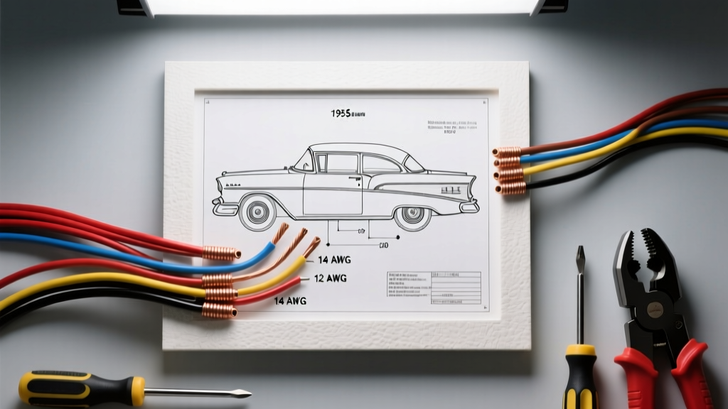
Introduction to the 1955 Chevy Electrical System
When consulting a 1955 Chevy wiring diagram, the most critical piece of historical context to remember is that 1955 marked Chevrolet's first year utilizing a 12-volt electrical system across its passenger car lineup. Whether you are restoring a Bel Air, 210, or 150, and whether it houses the legendary 265 cubic-inch V8 or the reliable 235 inline-six, your vehicle left the factory with a 12V system. This eliminates the need for a 6V-to-12V conversion, but it does mean that original 60-year-old cloth-covered or early plastic-jacketed wiring is likely brittle, cracked, and a severe fire hazard. This practical how-to guide will walk you through replacing the factory harness with a modern, GM-color-coded replacement harness, upgrading the fuse panel, and properly grounding the chassis.
Preparation: Reading the 1955 Chevy Wiring Diagram
Before cutting a single zip tie, lay out your new harness and compare it against the OEM 1955 Chevy wiring diagram. Original 1955 schematics utilized simple solid colors or basic tracers, which can make modern troubleshooting a nightmare. We highly recommend using a modern replacement harness (such as those from American Autowire or Painless Performance) that adheres to standard GM color codes. For instance, the ignition switch feed will be Pink, the headlight dimmer feeds will be Dark Blue (high) and Light Green (low), and the taillights will be Brown. Mapping these modern colors to your vintage components ensures that any future mechanic can easily service your Tri-Five using standard GM wiring literature.
Essential Tools and Wire Gauge Specifications
Classic cars require specific wire gauges to handle electrical loads without voltage drop, especially when upgrading to modern halogen headlights or high-torque starters. According to the SAE J1128 Standard for low-tension primary cable, automotive wire must handle high engine bay temperatures. Below is the specification chart for your 1955 Chevy rewire.
| Circuit Component | Wire Gauge (AWG) | Modern GM Wire Color | Recommended Fuse (ATO/ATC) |
|---|---|---|---|
| Headlights (High/Low) | 10 AWG | Dark Blue / Light Green | 20A |
| Taillights & Parking | 12 AWG | Brown / Light Blue | 15A |
| Ignition Switch Feed | 12 AWG | Pink | 15A |
| Horn Relay Feed | 14 AWG | Black | 15A |
| Radio / Accessory | 14 AWG | Yellow | 10A |
| Alternator Main Charge | 8 AWG or 6 AWG | Red | 60A (Mega Fuse) |
Step-by-Step Harness Installation Guide
Step 1: Engine Bay and Bulkhead Routing
- Remove the Old Harness: Disconnect the battery. Label all original wires connected to the generator, voltage regulator, and coil before removing them. Document the original firewall pass-through locations.
- Mount the Fuse Panel: The original 1955 Chevy utilized glass AGC fuses located under the dash or inline. Mount a modern 12-circuit or 18-circuit ATO/ATC blade fuse panel under the dash on the driver's side kick panel. This provides superior circuit protection and easier diagnostics.
- Route the Engine Bay Harness: Pass the engine harness through the factory firewall bulkhead hole. Use a rubber grommet and apply dielectric grease to the terminals to prevent moisture intrusion. Keep the harness at least 4 inches away from the exhaust manifolds, particularly on the 265 V8 models where heat soak is significant.
- Connect the Front Lighting: Route the headlight buckets and parking light wires through the factory radiator support channels. Secure with adhesive-backed loom clips every 8 inches.
Step 2: Dash Harness and Gauge Cluster Integration
- Instrument Cluster Wiring: The 1955 dash cluster features the speedometer, fuel, temperature, and oil pressure gauges. Connect the Pink ignition wire to the gauge cluster power feed.
- Sender Unit Verification: This is a critical failure point in Tri-Five restorations. Ensure your fuel, temp, and oil sender units are calibrated for a 12-volt system. A 6V sender on a 12V system will cause the gauges to peg past the maximum reading and potentially burn out the internal gauge coils. The standard GM fuel sender resistance for this era is 0-90 ohms.
- Turn Signal Integration: While early 1950s Chevys used dealer-installed turn signals, 1955 introduced column-integrated signals on many models. Connect the steering column turn signal harness to the main dash harness using the provided GM column connector (typically a 4-pin or 6-pin flat plug).
Step 3: Lighting and Rear Harness Deployment
- Route Under the Carpet: Run the rear body harness along the driver's side rocker panel, underneath the carpet and padding. Use split-loom tubing to protect the wires from sharp sheet metal edges and seat spring brackets.
- Taillight Connections: Connect the Brown wire to the taillight running light terminal, and the Dark Green (Right) and Yellow (Left) wires to the respective turn/stop signal terminals. The 1955 Chevy uses a single 1157 dual-filament bulb in the rear housing.
Upgrading from Generator to Alternator
The factory 1955 Chevy wiring diagram routes power through a generator and an external voltage regulator mounted on the radiator support. Modern electrical loads (electric fans, high-output fuel pumps, modern stereos) require an alternator upgrade. The most common and reliable swap is the Delco 10SI or 12SI internally regulated alternator.
- Main Output (BAT Terminal): Run an 8 AWG or 6 AWG red wire from the alternator BAT terminal directly to the starter solenoid battery post or the main fuse panel battery feed. Install a 60A Mega Fuse inline.
- Terminal 1 (Exciter/Field): Run a 14 AWG wire from Terminal 1 to the "IGN" terminal on the fuse panel. This provides the initial 12V "exciter" signal to turn the alternator on when the key is in the Run position. Wire an optional 10-ohm resistor in parallel if your dash lacks an "ALT" or "GEN" warning light bulb, as the bulb's resistance is sometimes required to excite older 10SI units.
- Terminal 2 (Voltage Sense): Run a 14 AWG wire from Terminal 2 directly to the main battery positive terminal or the main power distribution block. This tells the internal regulator exactly what the battery voltage is, preventing undercharging caused by voltage drop across long wire runs.
For detailed factory specifications on the original charging system before modification, consult the 1955 Chevrolet Passenger Car Shop Manual archived by the Old Car Manual Project.
Grounding Strategies for Classic Chevy Sheet Metal
The number one cause of dim headlights, erratic gauges, and slow cranking in a 1955 Chevy is poor grounding. Classic Chevy sheet metal was painted and assembled with seams that do not provide reliable electrical continuity. Do not rely on the hinges or body mounts for ground paths.
- Engine to Chassis: Use a minimum 4 AWG braided copper ground strap connecting the engine block (use an intake manifold bolt or cylinder head bolt) directly to the main chassis frame rail.
- Body to Chassis: Run a 10 AWG ground wire from the chassis to the cowl area under the dash, and another from the chassis to the rear trunk pan near the taillights.
- Component Grounding: When grounding the headlights, horn, or taillight housings, remove all paint and rust from the mating surface. Use a star washer between the ring terminal and the bare metal to bite into the steel and prevent vibration loosening. Apply a small dab of anti-corrosion grease over the terminal after tightening.
Troubleshooting Common Tri-Five Electrical Gremlins
Even with a flawless installation based on the 1955 Chevy wiring diagram, you may encounter issues. Use this diagnostic tree to isolate faults:
- Symptom: Headlights work on High, but not Low beam.
- Cause: Faulty floor-mounted dimmer switch or broken Light Green wire.
- Fix: Check for 12V at the dimmer switch input (Red). If present, check the Light Green output. The floor dimmer switch is exposed to moisture and road debris; replace with a sealed heavy-duty unit.
- Symptom: Turn signals blink rapidly, but bulbs do not illuminate.
- Cause: Poor ground at the front parking light housing or rear taillight housing.
- Fix: The 1157 bulb grounds through the metal base to the housing. Remove the housing, sand the interior mounting surface to bare metal, and run a dedicated 16 AWG pigtail ground wire from the bulb socket base to a known good chassis ground.
- Symptom: Fuel gauge reads "Empty" when the tank is full.
- Cause: Sender unit resistance mismatch or open ground at the fuel tank.
- Fix: Disconnect the sender wire at the tank. Ground the wire to the chassis. If the gauge pegs to "Full", the wiring is good, and the sender unit or tank ground is at fault. Ensure the fuel tank sending unit flange has a clean metal-to-metal connection to the tank, and the tank is grounded to the frame.
Authoritative References & Further Reading
Proper electrical work requires adherence to industry standards and factory data. The following resources were utilized to compile this installation guide:
- SAE International J1128 - Standard for Low Tension Primary Cable, dictating insulation temperature ratings and strand counts for automotive wire.
- 1955 Chevrolet Passenger Car Shop Manual - The definitive OEM source for original Tri-Five wiring schematics, generator output specs, and factory circuit routing.
- American Autowire Classic Update Kits - Industry-leading documentation on retrofitting modern fused circuits and GM-standard color codes into 1955-1957 Chevrolet chassis.