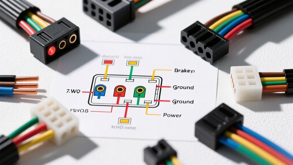
Introduction to Trailer Brake Circuits
Towing a trailer equipped with electric brakes requires more than just hitching up and driving away; it demands a fundamental understanding of the electrical circuits that keep you safe on the road. For beginners, staring at an electric brakes wiring diagram can feel like deciphering a foreign language. However, once you understand the core components—the brake controller, the 7-way connector, and the trailer electromagnets—the schematic becomes a straightforward roadmap. This guide breaks down the essential fundamentals of trailer brake wiring, focusing on industry-standard color codes, wire gauges, and critical connection points to ensure your rig stops safely and predictably.
How Electric Trailer Brakes Actually Work
Before tracing wires on a diagram, you must understand the load you are powering. Unlike hydraulic brakes that use fluid pressure, electric trailer brakes rely on electromagnets. When current flows through the brake magnet, it is attracted to the rotating steel drum. This friction pulls an actuating arm, forcing the brake shoes outward against the drum to slow the trailer.
Crucially, the brake controller in your tow vehicle does not send a simple 12-volt "on or off" signal. Instead, it uses Pulse Width Modulation (PWM). The controller rapidly pulses the 12V DC current on and off. By varying the width of these pulses (the duty cycle), the controller dictates the braking force. A 20% duty cycle provides light braking, while a 100% duty cycle locks the brakes. Your wiring diagram must account for this continuous, high-frequency pulsing, which is why proper wire gauge and clean connections are non-negotiable to prevent voltage drop and overheating.
Decoding the 7-Way RV Blade Wiring Diagram
The industry standard for towing vehicles with electric brakes is the 7-Way RV Blade connector, governed by the SAE J286 Standard. When looking at a wiring diagram for the tow vehicle's socket or the trailer's plug, the pinout is universally color-coded. Misinterpreting these colors is the leading cause of blown fuses and non-functional brakes.
| Pin / Clock Position | Function | Standard Wire Color | Recommended AWG | Circuit Notes |
|---|---|---|---|---|
| Pin 1 (7:00) | Ground Return | White | 10 or 8 AWG | Must be bonded to clean, bare metal on both vehicle and trailer frames. |
| Pin 2 (1:00) | Electric Brakes | Blue | 10 or 12 AWG | Carries the PWM signal from the brake controller to the trailer magnets. |
| Pin 3 (9:00) | Tail / Running Lights | Brown | 14 or 16 AWG | Often split into two brown wires on the trailer for left and right sides. |
| Pin 4 (11:00) | 12V Auxiliary Power | Black | 10 AWG | Used for charging trailer batteries or powering 12V interior accessories. |
| Pin 5 (5:00) | Right Turn / Stop | Green | 14 or 16 AWG | Combines turn signal and brake light circuits for the right side. |
| Pin 6 (3:00) | Left Turn / Stop | Yellow | 14 or 16 AWG | Combines turn signal and brake light circuits for the left side. |
| Pin 7 (Center) | Backup Lights / Aux | Purple | 14 or 16 AWG | Commonly wired to trigger a reverse lockout solenoid on surge brake couplers. |
The Brake Controller Pigtail: Under-Dash Wiring
While the 7-way connector handles the exterior routing, the brain of the operation is the electronic brake controller mounted under the dash. Most aftermarket controllers (and OEM integrated modules) utilize a standardized 4-wire pigtail. Understanding this specific sub-circuit is vital when reading the Tekonsha Installation Guides or similar manufacturer schematics.
- White Wire (Ground): This must be connected to a clean, unpainted metal surface on the vehicle's chassis or directly to the negative battery terminal. A poor ground here will cause the controller to display error codes or fail to output power to the blue wire.
- Black Wire (12V Power Input): This connects to the vehicle's positive battery terminal via an inline circuit breaker (typically 30A for single-axle, 40A for tandem-axle trailers). It provides the raw amperage required to energize the trailer magnets.
- Red Wire (Stoplight Switch Input): This is the trigger wire. It must be spliced into the "cold side" of the vehicle's brake light switch.
- Blue Wire (Brake Output): This carries the modulated PWM signal from the controller back to the 7-way connector (Pin 2).
The "Cold Side" vs. "Hot Side" Stoplight Switch Trap
A fundamental mistake beginners make when interpreting the red trigger wire on a wiring diagram is tapping into the wrong side of the brake pedal switch. The "hot side" of the switch often shares a circuit with cruise control disengagement, shift interlocks, or BCM (Body Control Module) polling. If you connect the red wire here, your brake controller will activate randomly, overheating the trailer magnets. You must use a multimeter to find the "cold side"—the wire that only shows 12 volts when the physical brake pedal is depressed and the brake lights illuminate.
Wire Gauge (AWG) and Voltage Drop Calculations
Wiring diagrams often specify minimum wire gauges, but beginners frequently ignore the physics of voltage drop over distance. The electric brake circuit (Blue wire) runs from the tow vehicle's dash, through the frame, across the umbilical cord, and down the entire length of the trailer to the axles. This can easily exceed 35 feet of total wire length.
According to standard etrailer Wiring FAQ guidelines and Ohm's Law, pushing 10 to 15 amps through a long, undersized wire results in significant voltage drop. If your brake controller outputs 12V, but the wire gauge is too thin, the magnets at the trailer axle might only see 9V, resulting in weak, inconsistent braking.
| Trailer Configuration | Minimum Wire Gauge | Recommended Wire Gauge | Circuit Breaker Rating |
|---|---|---|---|
| Single Axle (2 Magnets) | 12 AWG | 10 AWG | 30 Amp |
| Tandem Axle (4 Magnets) | 10 AWG | 10 AWG (or 8 AWG for long rigs) | 40 Amp |
| Triple Axle (6 Magnets) | 8 AWG | 8 AWG | 50 Amp |
Troubleshooting Common Diagram Misinterpretations
Even with a perfect wiring diagram, real-world variables can cause failures. Here is how to troubleshoot the two most common beginner errors using a digital multimeter (DMM):
1. The Phantom Ground Issue
Symptom: The trailer brakes work intermittently, or the brake controller displays a "No Trailer Connected" error despite the plug being seated.
The Fix: Beginners often assume the white ground wire (Pin 1) is simply a return path for the lights. In reality, the entire trailer brake circuit relies on the structural ground between the trailer frame and the tow vehicle frame. If the hitch ball is rusty or the trailer tongue is painted, the ground is compromised. Run a dedicated 10 AWG or 8 AWG white ground wire from the trailer's 7-way plug directly to a sanded, bare-metal spot on the trailer frame, and use a star washer to bite through any surface corrosion.
2. The Breakaway Kit Backfeed
Symptom: The trailer brakes lock up fully when the breakaway pin is pulled, but the brake controller in the cab shows zero output.
The Fix: The breakaway kit is a safety device wired directly to the trailer's 12V auxiliary battery (Pin 4 circuit) and spliced into the blue brake wire (Pin 2 circuit). When the trailer separates, the pin pulls, closing a switch that sends full battery voltage directly to the magnets. If your wiring diagram does not include a blocking diode between the breakaway switch and the brake controller output, the 12V backfeed can travel backward through the blue wire and fry the internal MOSFETs of your brake controller. Always verify that your schematic includes a diode, or use a breakaway kit with built-in backfeed protection.
Summary
Reading an electric brakes wiring diagram is entirely manageable when you break it down into its functional blocks: the power source, the PWM controller, the 7-way umbilical, and the electromagnet load. By strictly adhering to SAE color codes, respecting AWG requirements to prevent voltage drop, and ensuring a flawless chassis ground, you will build a trailer braking system that is both reliable and safe for the long haul.