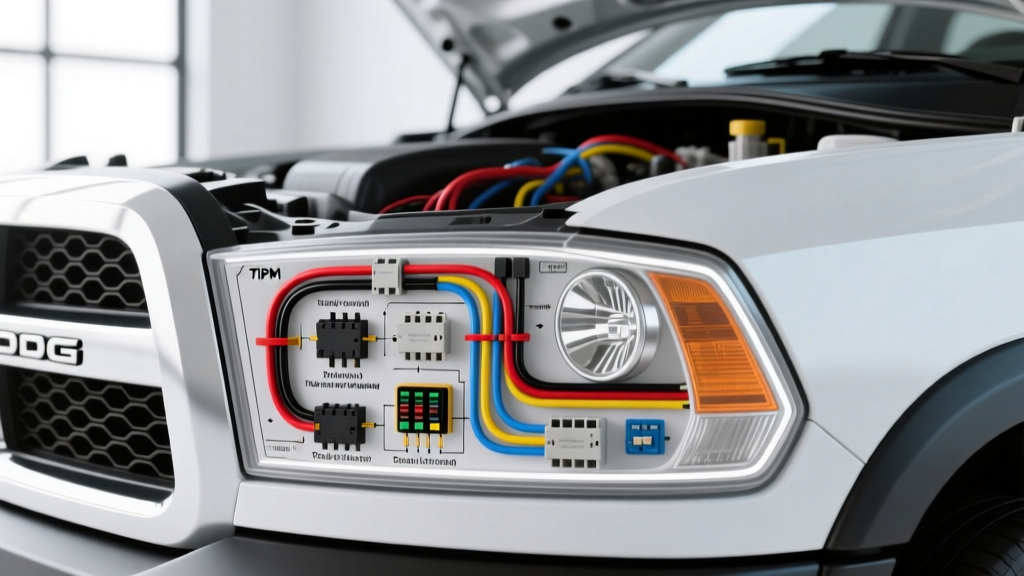
Understanding the 3rd-Gen Dodge Ram Headlight Circuit
When diagnosing illumination faults using a Dodge Ram headlight wiring diagram, it is critical to understand the architectural shift that occurred in the 2006-2008 (3rd Generation) models. Unlike older vehicles where the headlight switch carried high-current 12V+ feeds directly to the lamps, these trucks utilize a Totally Integrated Power Module (TIPM). The multifunction switch on the steering column merely sends a low-current logic signal or ground reference to the TIPM. The TIPM then processes this request and closes internal solid-state relays to route battery voltage to the headlight bulbs.
This multiplexed approach reduces the overall weight of the wiring harness and aligns with SAE J1128 standards for low-tension primary cable optimization. However, it also introduces unique failure modes. When a Dodge Ram experiences intermittent low beams, complete headlight failure, or high-beam lockout, the issue is rarely a simple blown fuse. It requires a systematic, step-by-step troubleshooting flow to isolate the fault between the switch logic, the TIPM internal relays, and the external 14 AWG feed circuits.
Step 1: Verify the Multifunction Switch Logic Signal
Before tearing into the engine bay wiring, you must verify that the TIPM is actually receiving the command to turn on the headlights. The multifunction switch (turn signal stalk) houses the headlight selector.
Testing the Switch Output
- Locate the Switch Connector: Access the C3 connector at the base of the steering column.
- Identify the Trigger Wire: The headlight request signal is typically carried on a Dark Green/Red (DG/RD) wire.
- Multimeter Test: Set your digital multimeter (DMM) to DC Volts. Back-probe the trigger wire with the ignition ON and the switch in the HEAD position. You should see a voltage drop to near 0.0V (indicating a ground signal to the TIPM) or a 12V logic high, depending on the specific TIPM software calibration.
If the switch is outputting the correct signal but the headlights remain dead, the fault lies downstream in the TIPM or the external harness.
Step 2: Analyze the TIPM Pinout and External Harness
The TIPM acts as the central nervous system for the truck exterior lighting. According to Chrysler Tech Authority diagnostic trees, if the logic signal is verified, the next step is to test the high-current outputs at the TIPM C7 connector, which routes directly to the front lighting harness.
2006-2008 Dodge Ram TIPM Headlight Pinout Table
| Circuit Function | TIPM Connector/Pin | Wire Color | Wire Gauge (AWG) |
|---|---|---|---|
| Left Low Beam Feed | C7, Pin 11 | Dark Green/White (DG/WT) | 14 AWG |
| Right Low Beam Feed | C7, Pin 12 | Dark Green/Orange (DG/OR) | 14 AWG |
| Left High Beam Feed | C7, Pin 13 | Dark Green/Tan (DG/TN) | 14 AWG |
| Right High Beam Feed | C7, Pin 14 | Dark Green/Pink (DG/PK) | 14 AWG |
| Headlight Ground (Chassis) | GND-101 (Fender) | Black (BK) | 12 AWG |
Inspect the C7 connector for signs of thermal damage. The TIPM is mounted in the engine bay and is exposed to extreme heat cycles. If the internal solder joints for the solid-state relays crack due to thermal expansion, the TIPM will fail to output voltage on these specific pins, even if the fuses test perfectly.
Step 3: Load Testing and Voltage Drop Analysis
A common mistake when using a Dodge Ram headlight wiring diagram is relying solely on an open-circuit voltage test. A broken wire with a single strand of copper still connected will show 12.6V on a high-impedance multimeter but will instantly collapse to 0V when a 55W halogen bulb (drawing roughly 4.5 Amps) is applied.
Performing the Voltage Drop Test
- Turn the headlights ON and confirm the TIPM is outputting voltage at the C7 pins.
- Move to the headlight bulb connector (H13 or 9007 bulb base).
- Place the positive probe of your DMM on the battery positive terminal, and the negative probe on the feed wire at the back of the headlight connector (back-probing).
- A healthy 14 AWG circuit should show a voltage drop of less than 0.2V. If you read 2V, 5V, or higher, you have severe resistance in the harness or a corroded TIPM pin.
- Repeat for the ground side: Place the positive probe on the battery negative terminal, and the negative probe on the headlight ground wire. The drop must be under 0.1V. If it exceeds this, clean the GND-101 ground point on the inner fender well, as corrosion here is a notorious cause of dimming and back-feeding through the high-beam filaments.
Step 4: The TIPM Bypass Harness Solution
When the troubleshooting flow confirms that the multifunction switch is sending the signal, the fuses are intact, but the TIPM C7 pins are dead, the internal TIPM relays have failed. Replacing the TIPM requires dealer-level programming and is highly expensive. The industry-standard, permanent fix endorsed by independent automotive electrical experts is installing a heavy-duty TIPM bypass relay harness.
Wiring the External Bypass Relay
This solution uses the failing TIPM output merely as a low-current trigger for a new, external 40A Bosch-style relay, which then pulls high current directly from the battery.
- Trigger Source: Tap into the existing Dark Green/White (Left Low Beam) wire at the headlight connector. This provides the 12V trigger signal or tap the parking light circuit if the low beam feed is completely dead.
- Relay Power (Pin 30): Run a new 10 AWG red wire directly from the battery positive terminal, protected by an inline 30A MAXI fuse mounted within 8 inches of the battery.
- Relay Output (Pin 87): Run a new 12 AWG wire from the relay to the low-beam feed wires at both left and right headlight connectors.
- Relay Ground (Pin 86): Securely ring-terminal this to a clean, bare-metal chassis point in the engine bay.
By executing this bypass, you completely remove the headlight amperage load from the aging TIPM circuit board, ensuring bright, consistent voltage at the H13 bulbs while retaining the OEM steering column switch functionality.
Common Symptom-to-Cause Decision Tree
To expedite your diagnostic process, cross-reference your specific symptoms with this decision tree before pulling out the wiring diagram:
- Symptom: Both low beams dead, high beams work.
Cause: Blown J-case low beam fuse in TIPM, or failed internal low-beam solid-state relay.
Action: Check fuse J12. If good, proceed to Step 4 for relay bypass. - Symptom: One low beam is dim, flickers, or goes out when high beams are activated.
Cause: High resistance at GND-101 causing current to back-feed through the opposing headlight high-beam filament.
Action: Perform ground-side voltage drop test. Sand and clean the inner fender ground point. - Symptom: Headlights remain ON after the truck is turned off and key is removed.
Cause: Internal TIPM relay shorted closed, or water intrusion into the C7 connector causing cross-circuit continuity.
Action: Disconnect C7. If lights stay on, replace TIPM. If lights go out, inspect C7 for green corrosion and apply dielectric grease. - Symptom: Headlights do not turn on, but the multifunction switch stalk feels loose.
Cause: Mechanical failure of the clock spring or the internal wiper contacts inside the multifunction switch assembly.
Action: Test logic signal at C3 connector as outlined in Step 1.
Summary of Diagnostic Flow
Troubleshooting modern Dodge Ram lighting circuits requires moving beyond simple fuse checks. By following this logical sequence—verifying the steering column logic signal, consulting the specific TIPM C7 pinout, performing rigorous voltage drop tests under load, and deploying a bypass harness when internal solid-state relays fail—you can accurately diagnose and permanently resolve headlight wiring faults. Always reference the factory wire color codes and adhere to SAE standards for wire gauge and overcurrent protection when modifying or repairing automotive lighting circuits.