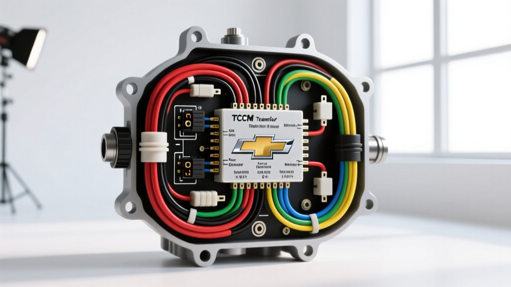
GM NVG246 & NVG263 Transfer Case Control Architecture
When diagnosing four-wheel-drive faults in GMT800 and GMT900 platforms, understanding the Chevy transfer case wiring diagram is critical for accurate electrical troubleshooting. General Motors transitioned from mechanical linkages to electronic shift-on-the-fly (ESOF) and Autotrac systems, primarily utilizing the New Venture Gear NVG246 (RPO NP8) and NVG263 (RPO NP4) transfer cases. These units rely on a centralized Transfer Case Control Module (TCCM) to interpret driver inputs from the dash-mounted Mode Select Switch (MSS), monitor planetary gear position via an encoder motor, and command internal range clutches alongside the front axle disconnect actuator.
Unlike simple relay-driven systems, the GM TCCM utilizes a solid-state H-bridge to control the encoder motor's direction and a multiplexed resistor network to read the dashboard switch. A single wiring fault, chafed harness, or corroded Delphi Packard connector can trigger the dreaded "Service 4WD" message and default the system into a fail-safe neutral or locked 4HI state. This guide provides an advanced technical deep dive into the 16-pin TCCM wiring schematic, circuit logic, and real-world diagnostic protocols.
16-Pin TCCM Connector Pinout & Wire Color Chart
The GMT800/GMT900 TCCM typically interfaces with the vehicle harness via a 16-cavity Delphi/Packard Metri-Pack 280 weather-sealed connector. Below is the definitive pinout reference for the NVG246/NVG263 control circuits. All signal wires utilize SAE J1128 GXL/TXL cross-linked polyethylene insulation to withstand underbody thermal cycling and chemical exposure.
| Pin | Circuit Function | Wire Color | AWG | Electrical Specification |
|---|---|---|---|---|
| A | Class 2 Serial Data | Yellow | 18 | 0-7V PWM, 10.4 kbps |
| B | Encoder Signal A | Tan | 18 | 0-5V Quadrature Pulse |
| C | Encoder Signal B | Light Blue | 18 | 0-5V Quadrature Pulse |
| D | 5V Reference (Encoder) | Brown | 18 | 5.0V ± 0.1V |
| E | Encoder / Sensor Ground | Black | 18 | < 0.05V Drop |
| F | Motor Control A | Dark Blue | 16 | H-Bridge Output (Max 8A) |
| G | Motor Control B | Yellow/Black | 16 | H-Bridge Output (Max 8A) |
| H | Ignition 1 (Run/Start) | Pink | 14 | 12V Battery (Switched) |
| J | Battery Positive (Hot) | Orange | 14 | 12V Battery (Constant) |
| K | Module Power Ground | Black/White | 14 | Chassis Ground (G103/G104) |
| L | Front Axle Actuator Ctrl | Light Green | 16 | Low-Side Driver (Ground) |
| M | Mode Switch Signal A | Gray | 18 | Multiplexed Resistor Ladder |
| N | Mode Switch Signal B | White | 18 | Multiplexed Resistor Ladder |
| P | Mode Switch Signal C | Dark Green | 18 | Multiplexed Resistor Ladder |
Encoder Motor Circuit Deep Dive & Signal Analysis
The encoder motor serves a dual purpose: it physically rotates the shift cam to engage the 2HI, 4HI, Neutral, and 4LO ranges, and it provides real-time positional feedback to the TCCM. The feedback mechanism relies on a resistive wiper board (early GMT800) or a Hall-effect sensor array (late GMT800/GMT900) that outputs two quadrature signals (Pins B and C).
Quadrature Signal Diagnostics (Pins B & C)
As the motor turns the cam, Pins B and C output a 0-5V square wave. The TCCM measures the phase relationship between Signal A (Tan) and Signal B (Light Blue) to determine the direction of rotation and the exact degree of cam travel. If you back-probe these circuits with an oscilloscope while commanding a shift, you should see clean, overlapping square waves. A flattened waveform or a drop in the 5V reference (Pin D, Brown wire) indicates internal wear on the encoder's wiper board or moisture intrusion in the motor's 5-way pigtail. According to Haynes automotive electrical diagnostic standards, any 5V reference dropping below 4.8V under load will cause the TCCM to abort the shift and set DTC C0327 (Encoder Circuit Malfunction).
H-Bridge Motor Control Logic
Pins F (Dark Blue) and G (Yellow/Black) are the high-current outputs from the TCCM's internal H-bridge. To shift into 4HI, the TCCM applies +12V to Pin F and grounds Pin G. To return to 2HI, the TCCM reverses polarity, applying +12V to Pin G and grounding Pin F. These 16 AWG circuits must handle the motor's stall current, which peaks around 6 to 8 amps. If the shift cam becomes physically bound due to degraded transfer case fluid or a worn shift fork, the motor will stall, drawing maximum amperage. The TCCM monitors this current draw; if it exceeds the threshold for more than 3 seconds, it cuts power to prevent harness meltdown and sets DTC C0308 (Motor A/B Circuit).
Front Axle Actuator Circuit & Thermal vs. Motorized
Pin L (Light Green, 16 AWG) controls the front axle disconnect. Early GMT800 trucks utilized a thermal actuator (a sealed cylinder containing a gas that expands when heated). The TCCM supplies 12V to the actuator, and the ground path passes through the transfer case range switch. Later models upgraded to a DC motorized actuator controlled directly by the TCCM via a low-side driver on Pin L. When diagnosing a no-4WD condition where the transfer case shifts but the front hubs do not lock, verify that Pin L receives a ground command from the TCCM while the ignition is in RUN and the MSS is in 4HI. A common failure point is the intermediate harness connector (C105) located near the transmission crossmember, which is highly susceptible to water ingress and terminal fretting corrosion.
Common Electrical Failure Modes & Diagnostic Trees
Use the following symptom-based decision trees to isolate electrical faults without unnecessarily replacing the TCCM or encoder motor.
Symptom: Service 4WD Illuminated Instantly on Key-On
- Step 1: Connect a scan tool and read TCCM codes. If C0305 or C0309 (Switch Circuit) is present, proceed to Step 2.
- Step 2: Back-probe the Mode Switch Signals (Pins M, N, P) at the TCCM. With the switch in 2HI, you should read specific voltage drops (typically 2.5V, 1.2V, and 0.6V depending on the internal resistor ladder).
- Step 3: If voltages read 0V or 5V (Open/Short), unplug the dash switch. Check the continuity of the Gray, White, and Dark Green wires back to the TCCM. A broken wire in the steering column shroud is the primary culprit.
Symptom: Motor Hums but Transfer Case Does Not Shift
- Step 1: This is rarely an electrical fault. The H-bridge is successfully delivering current (humming), but mechanical energy is not transferring to the planetary gear.
- Step 2: Inspect the encoder motor's nylon drive gear. The plastic teeth frequently strip, leaving the metal shift cam stationary while the motor spins freely.
- Step 3: Verify transfer case fluid level. Low fluid causes the shift cam to bind on the sector shaft, triggering a secondary electrical stall code (C0308).
Symptom: Intermittent Loss of 4WD in Cold Weather
- Step 1: Suspect the Front Axle Actuator circuit. If equipped with the older thermal actuator, the internal heating element degrades over time, requiring excessive current or failing to expand the locking collar in sub-freezing temperatures.
- Step 2: Measure the resistance of the thermal actuator. It should read between 10 and 15 Ohms. An open reading (OL) dictates actuator replacement.
Repair Protocols & Connector Service Standards
When repairing the Chevy transfer case wiring harness, standard twist-and-tape methods will fail due to the underbody environment. All repairs must utilize solder-seal heat shrink terminals or OEM Delphi crimp terminals with proper weather-pack seals. When re-seating the 16-pin TCCM connector, always apply a dielectric grease such as Nyogel 760G to the terminals to prevent galvanic corrosion and fretting. Ensure the TCCM mounting bracket is torqued to 10 Nm (89 lb-in) to maintain proper chassis grounding, and torque the encoder motor retaining bolts to 25 Nm (18 lb-ft) to prevent cam misalignment. For further diagnostic methodologies on serial data networks and module grounding, refer to SAE J1850 Class B Data Communication Network standards, which govern the TCCM's communication with the Powertrain Control Module (PCM) over the Class 2 serial data bus.