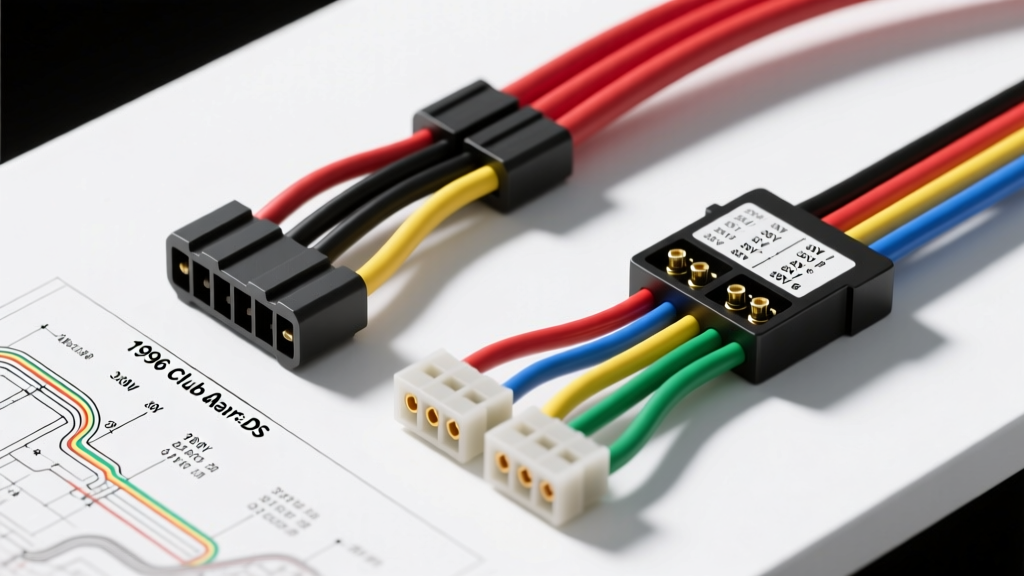
Understanding the 1996 Club Car DS Electrical Architecture
The 1996 Club Car DS represents a pivotal transition era in golf cart electrical design. During this model year, Club Car shifted away from older resistor-based speed control boxes toward advanced solid-state motor speed controllers, while still utilizing the iconic V-Glide throttle assembly on many early-production units before fully transitioning to the Inductive Throttle Sensor (ITS). For automotive and small electric vehicle (EV) technicians, interpreting the 1996 Club Car DS wiring diagram requires a firm grasp of both high-current 36V drive circuits and low-voltage logic control routing.
Whether you are restoring a fleet vehicle, troubleshooting a dead cart, or planning a high-torque motor upgrade, selecting the correct wiring harness and understanding the factory schematic is critical. A standard 36V DS system draws upwards of 300 amps under peak load, meaning that undersized wiring or degraded OEM connectors will result in severe voltage drop, melted insulation, and catastrophic controller failure. This guide serves as a comprehensive product comparison and selection resource for your 1996 DS wiring project, backed by Curtis Instruments controller specifications and industry-standard SAE wiring practices.
OEM vs. Aftermarket: Selecting the Right Wiring Harness
When rebuilding the electrical system of a 1996 Club Car DS, technicians must choose between a direct-fit OEM replacement harness and a heavy-duty aftermarket custom harness. The decision depends heavily on the cart's intended use case—standard neighborhood cruising versus heavy-duty utility or lifted off-road applications.
Harness Selection Comparison Chart
| Feature | OEM 14-Pin Replacement Harness | Heavy-Duty Silicone Custom Harness |
|---|---|---|
| Control Wire Gauge | 14 AWG (Standard Copper) | 12 AWG (Stranded Tinned Copper) |
| Insulation Material | PVC (Rated to 105°C) | Silicone (Rated to 200°C) |
| Connector Type | Standard AMP/Molex 14-Pin Block | Sealed Deutsch DT / AMP Superseal |
| Voltage Drop (50ft run) | ~0.25V at 10A | ~0.15V at 10A |
| Best Application | Stock 36V Restorations, Light Duty | 48V Conversions, High-Amp Upgrades |
| Installation Effort | Plug-and-Play (15 Minutes) | Requires Repinning & Routing (2+ Hours) |
Expert Verdict: If your 1996 DS is equipped with a stock 36V motor and standard controller, the OEM 14-pin harness is sufficient. However, if you are upgrading to a 400A+ aftermarket controller or converting to a 48V battery bank, the heavy-duty silicone harness is mandatory to prevent logic-circuit voltage drops that trigger the controller's low-voltage cutoff protection.
1996 Club Car DS Wiring Diagram Breakdown
The factory wiring schematic for the 1996 DS is divided into two distinct systems: the High-Current Drive Circuit and the Low-Voltage Control Circuit. Understanding the isolation between these two systems is the key to accurate troubleshooting.
1. High-Current Drive Circuit (Main Power)
The drive circuit is responsible for delivering raw amperage from the battery bank to the motor via the solenoid and controller. All wiring in this circuit must adhere to SAE J506 battery cable standards.
- Battery to Solenoid: 2 AWG flexible welding cable (Red). Routes from the main battery pack positive terminal to the solenoid's large input post.
- Solenoid to Controller B+: 2 AWG (Red). Exits the solenoid's large output post and terminates at the controller's main positive bus bar.
- Controller to Motor Armature/Field: 2 AWG (Yellow and Blue). The controller modulates the PWM signal to the motor. Yellow connects to the Armature (A1/A2), and Blue connects to the Field (F1/F2) for separate excitation (SepEx) or standard series wound configurations depending on the exact motor variant installed.
- Main Ground: 2 AWG (Black). Battery pack negative to the controller's B- terminal and chassis ground.
2. Low-Voltage Control & Throttle Circuit
The control circuit operates at pack voltage (36V) but draws minimal current (under 5 amps). It manages the solenoid coil activation, forward/reverse logic, and throttle signaling.
- Key Switch & Solenoid Coil: 14 AWG (Orange/Red). The key switch sends 36V to the solenoid's small activation terminal. Critical Note: A 250-ohm, 5W pre-charge resistor must be wired in parallel across the solenoid's large terminals to prevent capacitor inrush current from welding the contacts.
- Forward & Reverse (F&R) Switch: The 1996 F&R switch utilizes a 4-post or 6-post microswitch array. It physically reverses the current flow through the motor's field windings (Blue wires) while maintaining armature polarity.
- V-Glide Throttle Input: Early 1996 models use a V-Glide board with a series of microswitches and a variable resistor. Late 1996 models transition to the ITS (Inductive Throttle Sensor), which uses a 3-wire Hall-effect setup (5V reference, Ground, and Signal return).
Master Wire Color & Pinout Reference Chart
When repinning a 14-point connector or tracing a fault with a multimeter, use this definitive color-code reference for the 1996 solid-state DS platform. Always verify with a multimeter, as previous owners may have altered the harness.
| Wire Color | AWG Size | Origin | Destination | Function / Signal Type |
|---|---|---|---|---|
| Red | 2 AWG | Battery Pack (+) | Solenoid / Controller B+ | Main High-Current Positive |
| Black | 2 AWG | Battery Pack (-) | Controller B- / Chassis | Main High-Current Negative |
| Yellow | 2 AWG | Controller (M- / A-) | Motor Armature | Armature Drive (PWM Modulated) |
| Blue | 2 AWG | Controller (F+ / F-) | Motor Field | Field Excitation / Direction |
| Orange | 14 AWG | Key Switch | Solenoid Coil (+) | 36V Solenoid Activation Logic |
| White | 16 AWG | V-Glide / ITS | Controller Throttle Pin | Analog Throttle Signal (0-5V) |
| Green | 14 AWG | F&R Microswitch | Controller Interlock | Directional Logic Enable |
Common Failure Modes & Troubleshooting the '96 DS
Diagnostic work on the 1996 Club Car DS requires a systematic approach. Because the cart lacks an OBD-II port, technicians must rely on voltage-drop testing and continuity checks. Below is a symptom-cause-fix decision tree based on real-world field data compiled by the Buggies Gone Wild Electric Archives.
Symptom: Solenoid Clicks, But Cart Does Not Move
- Cause 1: Solenoid Contact Arcing. The internal copper contacts are pitted or welded. Fix: Test voltage drop across the large solenoid terminals while pressing the throttle. A drop greater than 0.5V indicates a failed solenoid. Replace with a heavy-duty 400A continuous-rated contactor.
- Cause 2: Controller High-Pedal Disable (HPD). If the throttle was depressed before turning the key, the controller locks out for safety. Fix: Release the pedal, turn the key off, wait 5 seconds, and restart.
- Cause 3: Blown Controller MOSFETs. Fix: Perform a diode check on the controller's main terminals. If B+ to M- reads a short circuit (0.00V), the internal power stage is destroyed and the controller requires replacement.
Symptom: Intermittent Power Loss Over Bumps
- Cause 1: V-Glide Board Wear. The carbon tracks on the early '96 V-Glide board wear down, causing open circuits in the throttle signal. Fix: Bypass the V-Glide entirely and retrofit an ITS (Inductive Throttle Sensor) pedal box, which uses a non-contact magnetic Hall-effect sensor for infinite lifespan.
- Cause 2: Loose 14-Pin Connector. The OEM plastic housing becomes brittle and pins back out. Fix: Extract the pins, crimp on new sealed terminals, and apply dielectric grease (SAE J1128 compliant) before reseating.
Expert Installation & Crimping Standards
When fabricating or repairing the 1996 Club Car DS wiring diagram layout, never use solder-only connections for high-current circuits. Solder is brittle and will fracture under the vibration of a golf cart chassis. Always use closed-end copper ring terminals crimped with a calibrated hydraulic or ratcheting hex-crimp tool. For the 2 AWG main battery cables, apply a layer of marine-grade heat shrink with an adhesive inner lining to prevent battery acid corrosion from creeping up the copper strands. Finally, ensure all logic wires are routed at least 4 inches away from the main PWM motor cables to prevent electromagnetic interference (EMI) from corrupting the throttle signal.