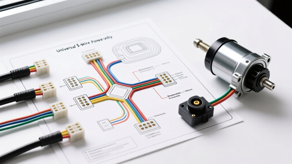
Understanding the Universal Power Window Wiring Diagram
Whether you are restoring a classic vehicle, upgrading manual windows to power, or replacing a failed OEM harness, understanding a standard power window wiring diagram is critical for a safe and reliable installation. Power window circuits draw significant amperage, especially when the glass binds in the weatherstripping or reaches the end of its travel. A poorly executed wiring job using undersized gauge wire or inadequate circuit protection can lead to melted insulation, voltage drops, and potential electrical fires.
This practical installation guide focuses on the ubiquitous universal 5-wire DPDT (Double Pole, Double Throw) rocker switch system and reversible 12V DC permanent magnet motors. By following the schematic logic and wire specifications outlined below, you will achieve a factory-grade installation that withstands the harsh environmental conditions inside a vehicle door cavity.
The Standard 5-Wire Power Window Switch Logic
Most aftermarket and universal power window kits utilize a 5-pin rocker switch. Internally, this is a center-off DPDT switch. The switch does not simply 'send power' to the motor; it manages both the 12V+ feed and the ground path, reversing the polarity across the motor's two terminals to dictate the direction of rotation.
- UP Position: 12V+ is routed to Motor Lead A, while Motor Lead B is routed to Ground.
- DOWN Position: 12V+ is routed to Motor Lead B, while Motor Lead A is routed to Ground.
- Center-Off: Both motor leads are disconnected from power, and the circuit is open, preventing parasitic draw.
Universal 5-Pin Switch Terminal Identification
| Pin Number | Function | Standard Wire Color | Recommended AWG | Connector Type |
|---|---|---|---|---|
| 1 (Center) | 12V+ Main Power Input | Red | 14 AWG | 1/4" Female Spade |
| 2 (Bottom) | Main Ground | Black | 14 AWG | 1/4" Female Spade |
| 3 (Top Right) | Motor Lead A (Up/Down) | Blue | 14 AWG | 1/4" Female Spade |
| 4 (Bottom Right) | Motor Lead B (Up/Down) | Green | 14 AWG | 1/4" Female Spade |
| 5 (Top Left) | Illumination / Daisy Chain | White | 18 AWG | 1/8" Female Spade |
Wire Gauge and Material Specifications
When routing wires through a vehicle chassis and into the door cavity, standard PVC-insulated wire is insufficient. According to the SAE J1128 standard for Low Tension Primary Cable, automotive wiring must withstand high ambient temperatures, vibration, and chemical exposure. For power window installations, always use TXL (Thin-wall Cross-linked) or SXL (Special Cross-linked) wire. TXL wire features a cross-linked polyethylene insulation that resists melting when soldering close to the terminal and offers superior abrasion resistance when pulled through tight door jamb conduits.
For the main power feed from the battery or fuse block to the cabin, use 12 AWG stranded copper. For the runs from the switch to the door motors, 14 AWG is the optimal balance of flexibility and current-carrying capacity for standard 20A-25A window motors. Never use solid-core wire; the constant flexing of the door hinge will cause solid copper to work-harden, snap, and short out against the chassis.
Step-by-Step Installation Procedure
Step 1: Main Power Routing and Circuit Protection
- Disconnect the negative battery terminal before beginning any chassis wiring.
- Run a 12 AWG TXL red wire from the positive battery terminal to the cabin. Route it through an existing firewall grommet to avoid piercing sheet metal.
- Install a 25A Type 1 Auto-Resetting Circuit Breaker within 6 inches of the battery connection. Unlike standard blade fuses, an auto-resetting breaker will trip if the window motor spikes in amperage due to frozen weatherstripping, but will reset automatically, allowing you to retry the operation without needing to replace a blown fuse.
Step 2: Navigating the Door Jamb Conduit
The most vulnerable point in any power window wiring diagram is the transition between the A-pillar and the door. Use a flexible rubber door jamb boot to protect the wiring harness.
- Measure and cut 14 AWG Blue and Green wires for the motor leads, adding 6 inches of slack for the door hinge articulation.
- Wrap the wires in split-loom tubing or Tesa tape to prevent chafing against the rubber boot.
- Feed the wires through the conduit, ensuring there is a gentle 'S' curve inside the boot to accommodate the door opening and closing without putting tension on the crimps.
Step 3: Switch Termination and Daisy Chaining
If you are installing a driver-side master switch panel and a passenger-side single switch, you must daisy-chain the power and ground.
- Crimp 1/4" fully insulated female spade connectors onto the 14 AWG wires using a proper ratcheting crimp tool. Avoid cheap plier-style crimpers that deform the terminal.
- Connect the Red (12V+) and Black (Ground) wires to the master switch. Use a parallel splice connector or a daisy-chain pigtail to run secondary 14 AWG Red and Black wires to the passenger switch.
- Connect the Blue and Green motor leads from the master switch to the corresponding passenger switch terminals. The passenger switch will interrupt and reverse these leads locally.
Step 4: Motor Connection and Weatherproofing
Inside the door cavity, moisture and condensation are guaranteed. Exposed spade connectors on the window motor will corrode within months, leading to high-resistance faults.
- Crimp Weather-Pack or Metri-Pack sealed connectors onto the Blue and Green motor leads.
- Plug the sealed connectors directly into the window motor housing.
- Secure the wiring harness to the inner door skin using adhesive-backed cable tie mounts, keeping the wires clear of the window regulator's scissor arms and the glass travel path.
Heavy-Duty Relay Integration for High-Amperage Motors
While the standard 5-wire diagram routes full motor current through the dash switch, heavy-duty applications (such as classic car conversions with heavy glass, or heavy-duty truck windows) can draw upwards of 25-30 amps under load. Running this current through a standard universal rocker switch will cause the internal copper contacts to overheat and melt.
For high-amperage setups, modify the power window wiring diagram to use the 5-pin switch only as a low-current trigger for a pair of 40A Bosch-style SPDT (Single Pole, Double Throw) relays. In this configuration, the switch only handles 1-2 amps to energize the relay coils (Pins 85 and 86), while the heavy 12 AWG motor current flows directly from the battery through the relay's high-current contacts (Pins 30 and 87/87a) to the motor. This vastly extends the lifespan of the dashboard switches and eliminates voltage drop at the motor, resulting in faster window travel speeds.
Diagnostic Troubleshooting: Voltage Drop and Amperage
If your newly installed power windows are operating sluggishly or the circuit breaker is tripping, do not immediately replace the motor. Consult the Haynes Automotive Electrical Manual guidelines for voltage drop testing.
- Symptom: Window moves slowly, but motor sounds normal.
Cause: High resistance in the ground circuit or binding regulator tracks.
Fix: Perform a voltage drop test across the ground wire. Set your multimeter to DC Volts. Place the red probe on the motor casing and the black probe on the negative battery terminal. Actuate the window. A reading above 0.2V indicates a poor ground connection or corroded terminal. Clean the chassis ground point with a wire brush and apply dielectric grease. - Symptom: Circuit breaker trips immediately upon reaching the top or bottom of the travel.
Cause: Faulty limit switch or excessive mechanical bind.
Fix: Universal motors rely on the mechanical stall of the regulator track to spike the amperage and trip the breaker (or rely on internal thermal breakers). Lubricate the window run channels with silicone spray. If the mechanical bind is normal, ensure your circuit breaker is rated correctly (typically 25A) and is not a fast-blow fuse.
By strictly adhering to this power window wiring diagram and utilizing automotive-grade materials, your installation will provide reliable, factory-quality operation for the life of the vehicle.