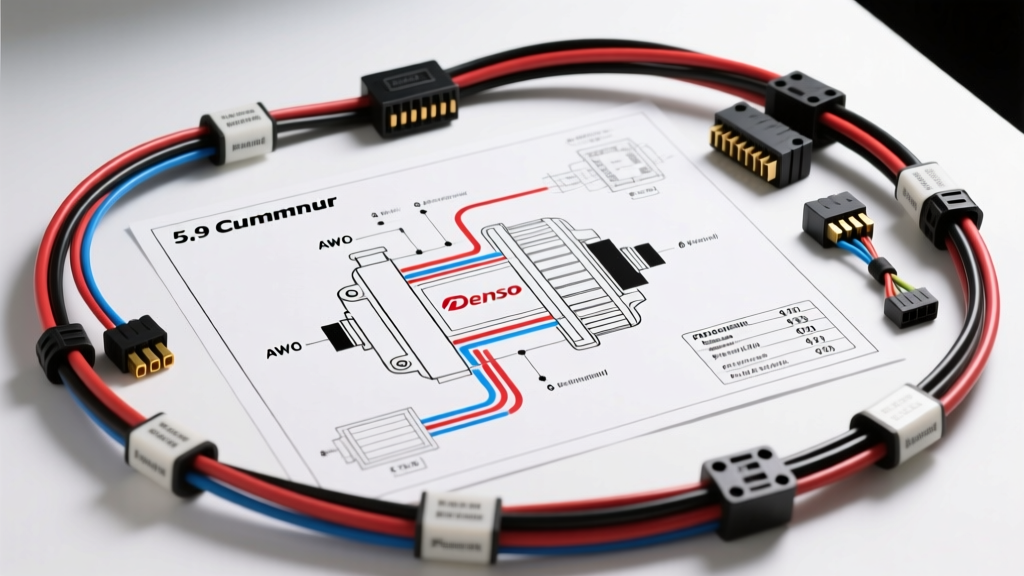
Why Upgrade the 5.9L Cummins Charging System?
The 5.9L Cummins ISB engine, found in Dodge Ram 2500 and 3500 trucks from 1998.5 through 2007, is legendary for its mechanical durability. However, the factory charging system is a well-documented weak point for owners running heavy aftermarket accessories. The stock Denso alternator typically peaks at 117 amps, which is woefully inadequate for modern RV setups, heavy-duty winching, off-road lighting arrays, and high-draw air compressors. When you push the stock unit past its continuous duty cycle, you risk stator burnout, diode failure, and ultimately, a stranded vehicle.
Upgrading to a high-output 200A to 250A alternator is a common modification. However, simply bolting on a larger unit without understanding the 5.9 Cummins alternator wiring diagram and the Powertrain Control Module (PCM) integration will result in check engine lights, idle droop, and potential electrical fires. This guide provides the exact wiring schematics, wire gauge requirements, and PCM integration strategies necessary to execute a bulletproof high-amp charging system upgrade.
Decoding the Stock Denso 6-Pin Connector
Before modifying the harness, you must understand the factory Denso 6-pin plug. The Dodge PCM relies on specific feedback loops from the alternator to manage engine idle speed and monitor charging system health. The stock wiring harness utilizes the following pinout configuration:
| Pin | Function | OEM Wire Color | Description & PCM Logic |
|---|---|---|---|
| 1 | IG (Ignition) | Black/White | Switched 12V+ source. Wakes up the alternator voltage regulator. |
| 2 | L (Lamp) | Dark Green | Dashboard charge indicator lamp circuit. |
| 3 | S (Sense) | Red/White | Battery voltage sense. Reads directly from the B+ terminal or battery post. |
| 4 | G (Ground) | Black | Regulator logic ground. |
| 5 | C (Control) | Dark Blue | PCM load request signal (used in later ISB models for load shedding). |
| 6 | FR (Field Rate) | Light Green/Orange | Critical: Sends a duty-cycle square wave back to the PCM indicating alternator load. |
According to Denso Global Alternator Specifications, the FR (Field Rate) signal is a 12V square wave that varies in frequency based on the magnetic field strength inside the alternator. If you install a generic '1-wire' alternator and abandon this plug, the PCM loses the FR signal. This triggers a P2509 or P0562 code, and the ECM will fail to bump the idle speed when high electrical loads are applied, leading to engine stalling at stoplights.
The High-Amp Upgrade Wiring Diagram & Execution
For this upgrade project, we recommend utilizing a high-amperage alternator that retains the Denso 6-pin case style (such as those built by Nations Starter & Alternator or DC Power). This allows you to plug the factory harness directly into the new unit while utilizing upgraded internal stators and rectifiers. If you are using a true 1-wire remote-sense alternator, you will need to build a custom dummy-load harness for the FR wire, which we cover in the troubleshooting section.
Step 1: Upgrading the Main Charge Wire (B+)
The factory B+ charge wire is typically 8 AWG or 6 AWG, which is a severe bottleneck for a 200A+ alternator. Pushing 220 amps through an 8 AWG wire will cause massive voltage drop and melt the insulation.
- Wire Selection: Use 2/0 AWG (00 AWG) copper welding cable. It offers high strand counts for extreme flexibility and vibration resistance in the engine bay.
- Routing: Route the 2/0 AWG cable from the alternator B+ terminal directly to the starter relay or the positive battery post. Avoid routing near the exhaust manifold or steering shaft U-joints.
- Fusing: Per SAE J541 Truck Electrical Systems standards, you must install an overcurrent protection device within 7 inches of the battery positive terminal. Use a 250-Amp ANL or Class T fuse in a marine-grade block.
Step 2: Upgrading the Sense Wire (Pin 3)
The stock Red/White sense wire reads voltage at the alternator output stud or the under-hood fuse block. When upgrading to a high-amp system, voltage drop across the factory fusible links and grid heater relays can trick the regulator into overcharging the batteries. Splice a new 10 AWG primary wire into the Pin 3 sense circuit and route it directly to the positive battery post, protected by an inline 15A maxi-fuse. This ensures the regulator reads true battery state-of-charge.
Step 3: Establishing a Bulletproof Ground
High-amp alternators require massive ground paths. The factory alternator-to-engine block grounding is often compromised by paint, corrosion, and vibration.
- Clean the alternator mounting ears and the engine block mating surfaces down to bare metal using a wire wheel and brake cleaner.
- Install a dedicated 1/0 AWG ground strap from the alternator casing directly to the passenger side cylinder head.
- Verify the main engine-to-chassis and battery-to-chassis ground straps are upgraded to 2/0 AWG to handle the return current without causing ECU interference.
AWG Sizing Chart for Cummins Charging Systems
Selecting the correct wire gauge is dictated by the maximum amperage and the total length of the wire run (positive and ground combined). Refer to this chart based on a maximum allowable voltage drop of 0.2V (approx 1.5% of a 14V system):
| Alternator Output | Wire Run (One Way) | Minimum AWG Required | Recommended Fuse |
|---|---|---|---|
| 117A (Stock) | 3 Feet | 6 AWG | 150A Mega |
| 165A | 4 Feet | 4 AWG | 200A ANL |
| 200A | 5 Feet | 1/0 AWG | 250A Class T |
| 250A+ | 6+ Feet | 2/0 AWG | 300A Class T |
Troubleshooting Common Upgrade Failure Modes
Even with a perfect physical installation, electrical gremlins can arise if the PCM integration is ignored. Here is how to diagnose the most common post-upgrade issues:
Symptom: Idle Droop and Dimming Lights at Stoplights
Cause: The PCM is not receiving the FR (Field Rate) signal on Pin 6, or the IG (Ignition) wire on Pin 1 is dropping below 11V due to a bad ignition switch.
Fix: Use an oscilloscope to probe the Light Green/Orange FR wire at the PCM connector (C3, Pin 29 on 3rd Gen Rams). You should see a clean 0-12V square wave. If you installed a 1-wire alternator, you must install a 470-ohm pull-up resistor between a switched 12V source and the FR wire to simulate the field signal and keep the PCM out of limp mode.
Symptom: Alternator Whine in Audio System / ECU Interference
Cause: Ground loops created by mixing different ground potentials, or using solid-core wire instead of multi-strand copper for the sense circuit.
Fix: Ensure all audio amplifiers and ECU sensors share a common ground plane on the engine block. Verify the 2/0 AWG ground strap from the block to the chassis is free of rust. Apply dielectric grease to all ring terminals to prevent micro-arcing.
Symptom: B+ Terminal Melting or Discoloration
Cause: Improper crimping of the 2/0 AWG cable or insufficient torque on the alternator output nut.
Fix: Never use mechanical pliers to crimp high-amperage lugs. Use a hydraulic crimper with hex dies to ensure a cold-weld compression. The alternator B+ nut (typically M8 or 5/16-18) must be torqued to exactly 12-15 ft-lbs using a calibrated torque wrench. Seal the termination with adhesive-lined marine heat shrink to prevent moisture intrusion and copper oxidation.
Final Verification and Testing
Once the physical wiring and PCM integration are complete, perform a loaded voltage drop test. Start the 5.9L Cummins, turn on the HVAC blower to maximum, engage the high-beam headlights, and activate the rear window defroster. Using a digital multimeter, measure the voltage directly at the alternator B+ post, and then measure at the positive battery post. The difference (voltage drop) must be less than 0.20V DC. If the drop exceeds this threshold, re-evaluate your crimp quality and terminal cleanliness. By strictly adhering to this 5.9 Cummins alternator wiring diagram and upgrade protocol, your high-amp charging system will provide reliable, continuous power for the most demanding off-grid and towing applications.