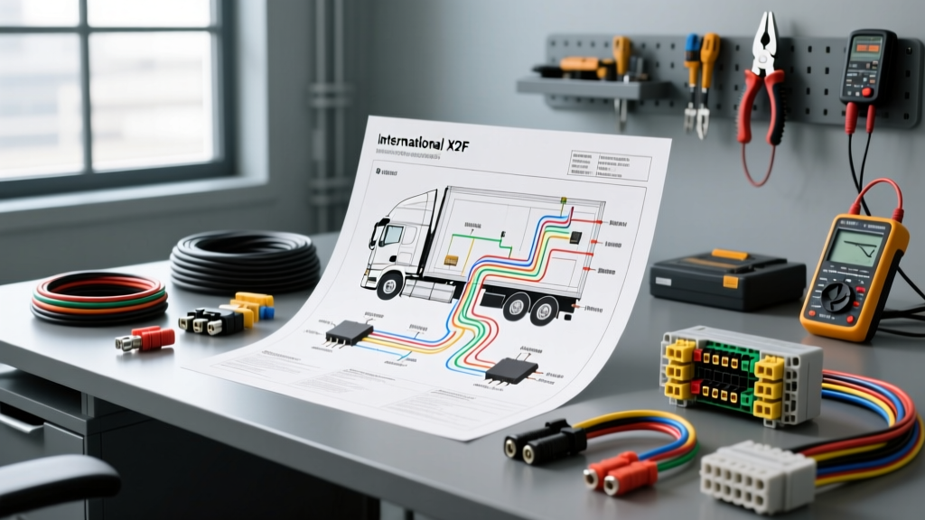
The True Cost of International Truck Wiring Diagram Schematic PDF Access
When diagnosing complex electrical faults on heavy-duty Navistar platforms, securing an accurate international truck wiring diagram schematic pdf is the critical first step. Unlike light-duty passenger vehicles, commercial trucks like the International ProStar, LoneStar, and HX series feature multiplexed electrical architectures, J1939 CAN-bus networks, and proprietary body controller modules. However, acquiring these schematics and possessing the right tools to interpret them represents a significant investment for independent shops and owner-operators.
OEM vs. Aftermarket Schematic Access Costs
Navistar dealerships utilize the proprietary International Service Portal and ServiceMaxx software, which typically costs upwards of $1,200 to $1,500 annually for full enterprise access. This provides live, interactive wiring diagrams rather than static PDFs. For independent heavy-duty repair facilities, subscribing to OEM portals is often cost-prohibitive.
Instead, most independent technicians turn to comprehensive aftermarket databases. Platforms like Mitchell1 TruckSeries or Diesel Laptops offer access to OEM-equivalent International truck wiring diagram schematic PDF bundles for approximately $250 to $350 per month. While cheaper than OEM portals, these subscriptions still represent a substantial overhead. Beware of third-party vendors selling 'lifetime access' USB drives for $50 to $100; these typically contain outdated, rasterized (scanned) PDFs that lack search functionality and layer management, making them nearly useless for tracing complex 120-pin ECM circuits.
Software Requirements for Schematic PDF Analysis
Not all PDFs are created equal in the realm of automotive electrical diagnostics. When you download an international truck wiring diagram schematic pdf, you must verify whether it is a Vector or Raster file.
- Vector PDFs: Generated directly from Navistar's CAD systems. They allow infinite zooming without pixelation, which is mandatory when reading 8-point font pin designations on a dense 120-pin Engine Control Module (ECM) connector diagram.
- Raster PDFs: Scanned images of older paper manuals. Zooming in results in blurred lines, making it impossible to distinguish between a solid wire and a dashed (shielded or optional) wire.
Furthermore, advanced Navistar chassis schematics utilize layered PDFs. You will need a robust PDF reader like Adobe Acrobat Pro to toggle layers on and off. For example, you can isolate the 'Power Distribution' layer and hide the 'CAN-Bus Data' layer to declutter the schematic while tracing a blown fuse to the cab HVAC blower motor.
Essential Diagnostic Tools for Navistar Platforms
Possessing the schematic is only half the battle. To physically test the circuits detailed in the international truck wiring diagram schematic pdf, you must invest in heavy-duty specific diagnostic tools. Standard automotive tools often fail or cause damage on commercial platforms.
Multimeters and Breakout Boxes
A standard $20 multimeter lacks the input impedance and durability required for heavy-duty ECM diagnostics. You need an automotive-grade Digital Multimeter (DMM) like the Fluke 88V Automotive Multimeter. It features a 10 Megohm input impedance to prevent drawing current and damaging sensitive MaxxForce engine sensors, alongside a 1000V CAT III safety rating necessary for testing heavy-duty alternator outputs and regenerative braking circuits.
Additionally, testing the J1939 CAN-bus requires a 9-pin diagnostic connector breakout box. This allows you to measure CAN-High and CAN-Low terminating resistances (which must read exactly 60 ohms across pins C and D) without back-probing and risking terminal damage.
Terminal Back-Probes and Weather Seals
International trucks heavily utilize Deutsch DT, DTM, and Ampseal connectors. Jamming standard sewing needles or paperclips into these connectors to back-probe a circuit will permanently deform the female terminal tines, leading to future intermittent connection failures and moisture intrusion. You must invest in a dedicated heavy-duty back-probe kit featuring 1.0mm, 1.5mm, and 2.8mm blade probes designed to slip past the silicone weather seals without compromising the connector integrity.
Case Study: Tracing a MaxxForce 13 EGR Valve Circuit
To demonstrate the practical application of an international truck wiring diagram schematic pdf, let us examine a common fault: an inoperative Exhaust Gas Recirculation (EGR) valve on a ProStar chassis equipped with a MaxxForce 13 engine.
According to the OEM schematic, the EGR valve motor is controlled by a Pulse Width Modulation (PWM) signal from the ECM. The circuit breakdown is as follows:
- ECM Pin 42 (EGR Motor PWM Control): Wire Color BU/WH (Blue with White tracer), 18 AWG.
- ECM Pin 11 (Actuator Power Feed): Wire Color OR (Orange), 12 AWG. Fed directly from the battery distribution box via a 20A fuse.
- ECM Pin 119 (Chassis Ground): Wire Color BK (Black), 12 AWG. Grounded to the left frame rail.
Diagnostic Procedure: Using your DMM, back-probe the OR (12 AWG) power wire at the EGR connector. With the key on, engine off (KOEO), you should read battery voltage (approx. 12.6V). Next, check the BK (12 AWG) ground wire. Perform a voltage drop test across the ground circuit while commanding the EGR valve via a bi-directional scan tool. A voltage drop exceeding 0.1V on the ground side indicates high resistance, often caused by corrosion at the frame rail ground stud—a notorious failure point on ProStar models operating in winter salt environments.
Tool Cost & Specification Matrix
| Tool / Resource | Estimated Cost | Application on International Trucks | Technical Specification |
|---|---|---|---|
| Aftermarket PDF Schematic Subscription | $250 - $350 / month | Access to Vector-based chassis & engine wiring diagrams | Must include interactive search & layer toggling |
| Automotive DMM (e.g., Fluke 88V) | $400 - $500 | Testing ECM sensors, PWM signals, and alternator outputs | 10 Megohm impedance, 1000V CAT III, Min/Max recording |
| Heavy-Duty Back-Probe Kit | $80 - $150 | Safe circuit testing at Deutsch and Ampseal connectors | Includes 1.0mm, 1.5mm, 2.8mm, and 4.8mm blade probes |
| 9-Pin J1939 Breakout Box | $120 - $200 | CAN-bus terminating resistance and voltage analysis | Compliant with SAE J1939 Standards for heavy-duty networks |
| OEM ServiceMaxx Software | $1,200+ / year | Bi-directional controls, parameter programming, live data | Requires Nexiq or Noregon JPRO VCI adapter (Sold separately) |
Expert Insights on Navistar Harness Degradation
When utilizing an international truck wiring diagram schematic pdf to trace a fault, you must understand the physical routing of the harness. On International ProStar and LoneStar models, the main engine-to-chassis harness passes through the firewall bulkhead connector (often a 30-pin or 40-pin Ampseal). This area is highly susceptible to vibration-induced chafing against the steering gear box and hydraulic lines.
If your schematic indicates a short to ground on a 5V reference circuit (typically a Grey or Grey/Black wire, 18 AWG), do not immediately suspect the ECM. Inspect the harness loom where it secures to the left frame rail. Navistar uses split-loom corrugated tubing, which can degrade under high under-hood temperatures (exceeding 220°F near the turbocharger). When replacing damaged sections, always use high-temperature, flame-retardant nylon braided sleeving and secure it with adhesive-lined heat shrink tubing to maintain the OEM IP67 weatherproof rating.
Ultimately, mastering heavy-duty electrical diagnostics requires more than just downloading a PDF. It requires a financial and technical commitment to the right software, precision testing equipment, and an intimate understanding of Navistar's specific wire color codes and connector architectures. By aligning your tool investments with the demands of the schematics, you can drastically reduce diagnostic time and eliminate costly 'parts-swapping' guesswork.