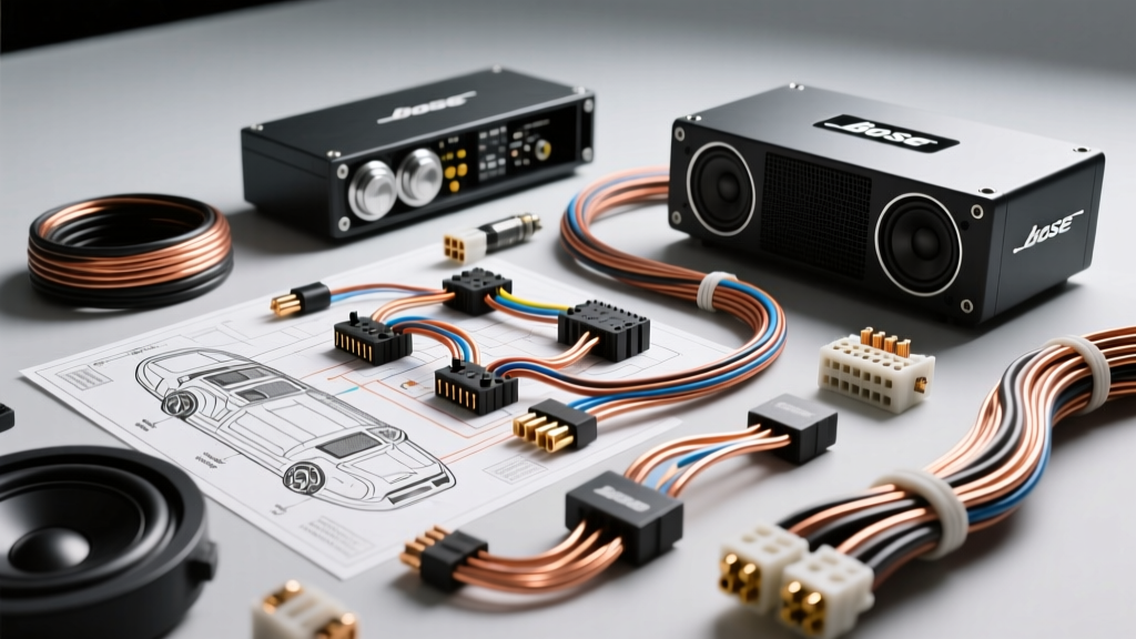
The Hidden Dangers of Bose Factory Audio Integration
When technicians and DIY enthusiasts search for a factory amp wiring bose car amplifier wiring diagram, they are often unprepared for the proprietary architecture hidden beneath the surface. Unlike standard aftermarket amplifiers that rely on simple RCA inputs and 12-volt remote turn-on leads, Bose factory audio systems utilize complex signal processing, active crossovers, data-bus volume controls, and proprietary impedance matching. Treating a Bose amplifier like a generic 4-channel amp is a fast track to destroyed tweeters, fried infotainment modules, and severe electrical hazards.
This guide focuses on the critical safety warnings, common integration mistakes, and precise wiring specifications required when working with factory Bose systems, specifically focusing on the widely modified General Motors (GM) and Nissan/Infiniti Bose architectures.
Critical Safety Warnings Before You Cut a Single Wire
Automotive electrical systems are highly integrated networks. Splicing into the wrong harness near the Bose amplifier can trigger catastrophic failures far beyond the audio system.
Airbag (SIR) Module Interference
In many GM trucks and SUVs (e.g., Silverado, Tahoe, Yukon), the Bose amplifier is mounted under the center console or behind the rear seats, in close proximity to the Supplemental Inflatable Restraint (SIR) Sensing and Diagnostic Module (SDM). The SIR system utilizes specialized, shielded yellow wiring harnesses. According to the GM Body Builder Guide, tapping into or improperly grounding near the SIR harness can alter the module's resistance, potentially causing an accidental airbag deployment or disabling the system entirely. Always maintain a minimum 6-inch clearance from any yellow SIR wiring and never use piercing splice connectors near the SDM.
Active Noise Cancellation (ANC) Feedback Loops
Late-model vehicles equipped with Bose (2014+ GM trucks, Honda/Acura platforms) frequently feature Active Noise Cancellation (ANC). The system uses cabin microphones to detect engine drone and sends an out-of-phase cancellation signal through the factory speakers. If you tap the speaker wires after the Bose amplifier to feed an aftermarket subwoofer via a Line Output Converter (LOC), the ANC system will interpret the subwoofer's bass as engine noise. It will then send aggressive, out-of-phase low-frequency signals back through the system, creating a destructive feedback loop that can instantly bottom out your subwoofers and damage your hearing. You must disable the ANC module or use a DSP with ANC-cancellation firmware before integrating aftermarket bass.
Decoding the Diagram: 3 Fatal Wiring Mistakes
Mistake 1: Misidentifying Class 2 / GMLAN Data vs. Analog Audio
A common error when reading a Bose car amplifier wiring diagram is assuming all small-gauge wires entering the amplifier are audio signals. In GM applications, volume, fade, balance, and equalization data are transmitted via the Class 2 serial data bus or GMLAN (often a Tan or Purple/White 18 AWG wire). Tapping into this data line expecting an audio signal will yield zero sound and can introduce noise that crashes the vehicle's infotainment network. Audio signals are strictly carried on twisted pairs, while data lines are single conductors.
Mistake 2: Ignoring the 8-Ohm vs. 2-Ohm Impedance Mismatch
Bose factory speakers are rarely the standard 4-ohm impedance found in aftermarket audio. Many Bose systems utilize 2-ohm voice coils to extract maximum power from low-voltage factory amplifiers, while some tweeters and mid-ranges are wired in series to present an 8-ohm load. If you replace a blown 2-ohm Bose speaker with a standard 4-ohm aftermarket speaker, the factory amp will run hotter and clip earlier. Conversely, wiring an 8-ohm Bose speaker to a standard aftermarket 4-ohm amplifier channel will result in a 50% loss of output power. Always verify impedance with a digital multimeter before connecting new drivers.
Mistake 3: Destroying Twisted-Pair Shielding
To prevent Electromagnetic Interference (EMI) and alternator whine, Bose analog audio input wires are manufactured as twisted pairs. As outlined in SAE J1113 standards for automotive EMC, untwisting these wires more than 1 inch from the connector breaks the common-mode rejection ratio (CMRR). If you are extending wiring for a DSP integration, you must maintain the twist rate (typically 10 to 15 twists per foot) and use shielded twisted-pair (STP) cable to prevent high-frequency alternator whine from entering the audio path.
GM Bose 8-Channel Amplifier Pinout & Wire Color Reference
The following table details the pinout for a standard GM Bose 8-Channel Amplifier (commonly found in 2007-2013 Silverado, Tahoe, and Escalade platforms). This reference is critical for identifying power, ground, data, and high-level audio outputs.
| Connector | Pin | Function | Wire Color | AWG |
|---|---|---|---|---|
| C1 (Power/Data) | A | Battery Positive (B+) | Red | 12 AWG |
| C1 (Power/Data) | B | Ground | Black/White | 12 AWG |
| C1 (Power/Data) | C | Class 2 Serial Data | Tan | 18 AWG |
| C1 (Power/Data) | D | Amplifier Enable (Remote) | Brown/White | 18 AWG |
| C2 (Audio Out) | A | Left Front Speaker (+) | Light Green | 18 AWG |
| C2 (Audio Out) | B | Left Front Speaker (-) | Dark Green/White | 18 AWG |
| C2 (Audio Out) | C | Right Front Speaker (+) | Gray | 18 AWG |
| C2 (Audio Out) | D | Right Front Speaker (-) | Dark Green/Black | 18 AWG |
| C2 (Audio Out) | E | Left Rear Speaker (+) | Light Blue | 18 AWG |
| C2 (Audio Out) | F | Left Rear Speaker (-) | Dark Blue/White | 18 AWG |
Proper Integration: Line Output Converters (LOCs) and DSPs
Because Bose amplifiers feature built-in crossovers and heavy factory equalization, you cannot simply tap the speaker outputs to feed a clean, full-range signal to an aftermarket amplifier. Doing so will result in a mid-bass heavy, rolled-off high-frequency response. To properly integrate a DSP or aftermarket amp, MECP-certified installers recommend the following protocol:
- Use an Active LOC: Devices like the Audiocontrol LC7i or PAC RP77-CH11 can sum the factory crossover signals back into a flat, full-range pre-amp signal.
- Defeat the Factory EQ: Many modern DSPs (like the Helix P SIX DSP) feature 'Virtual Channel Routing' and built-in de-EQ software that can analyze the Bose output via RTA microphone and invert the factory tuning curve.
- Maintain the Factory Load: If you are bypassing the Bose amp entirely, you must install dummy load resistors (typically 2-ohm or 4-ohm, 10-watt ceramic resistors) on the head unit outputs to prevent the infotainment system from throwing a diagnostic trouble code (DTC) and muting the audio.
Expert Troubleshooting Decision Tree
Use this diagnostic tree to identify and resolve common Bose integration failures:
- Symptom: Massive, booming bass feedback that shakes the vehicle when the engine is running.
Cause: Active Noise Cancellation (ANC) loop.
Fix: Locate the ANC module (usually in the rear headliner or under the dash) and disconnect its microphone inputs, or flash the ECU to disable the ANC feature. - Symptom: High-pitched alternator whine that increases with engine RPM.
Cause: Ground loop or destroyed twisted-pair shielding.
Fix: Ensure the aftermarket LOC and DSP are grounded to the exact same bare-metal chassis point as the factory Bose amplifier. Re-twist any extended audio input wires. - Symptom: Audio cuts out completely when the volume is turned above level 15.
Cause: Class 2 Data Bus collision or OEM speaker protection mode.
Fix: Check for pierced insulation on the Tan (Class 2) wire. Ensure aftermarket speaker impedance matches the factory 2-ohm or 8-ohm specifications to prevent the Bose amp's internal thermal protection from triggering.
Working with a Bose car amplifier wiring diagram requires patience, precision, and a deep respect for the vehicle's integrated networks. By avoiding these common mistakes and adhering to strict safety protocols, you can successfully upgrade your audio system without compromising the vehicle's electrical integrity.