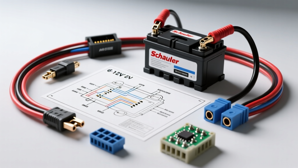
Understanding the Schauer 6/12V Dual-Voltage Architecture
Schauer linear battery chargers are legendary in the automotive and marine industries for their robust, transformer-based designs. Unlike modern high-frequency switch-mode chargers, classic Schauer units rely on heavy copper step-down transformers, silicon rectifier bridges, and analog ammeter shunts. For automotive electricians and classic car restorers, understanding the wiring diagram 6 12 volt schauer battery charger schematic is essential when building permanent garage charging stations, integrating dual-bank RV charging systems, or safely maintaining 6-volt classic vehicle electrical systems alongside 12-volt modern chassis batteries.
This practical installation guide bridges the gap between the internal charger schematic and the external vehicle wiring harness. We will cover how to safely route DC output, size your overcurrent protection, and integrate isolation relays to prevent backfeeding between dual-voltage battery banks.
Decoding the 6 12 Volt Schauer Battery Charger Schematic
When interpreting the wiring diagram 6 12 volt schauer battery charger schematic, technicians must first identify the secondary winding topology of the main step-down transformer. Most dual-voltage Schauer units utilize a center-tapped secondary winding.
- 12V Tap (Full Winding): Utilizes the entire secondary coil, outputting approximately 13.8V to 15.2V AC (depending on the load and specific model), which is then rectified to pulsating DC for 12V lead-acid charging.
- 6V Tap (Center Tap): Draws from the center point of the secondary winding to one end, halving the AC voltage to safely charge 6V golf cart, tractor, or classic automobile batteries without boiling the electrolyte.
- Rectifier Bridge: Typically consists of four stud-mounted silicon diodes (or a single integrated bridge module) rated for 35A to 50A at 200V PRV (Peak Reverse Voltage).
- Ammeter Shunt: A precision resistor wired in series with the negative DC output. It creates a millivolt drop (usually 50mV at full scale) that the analog panel meter reads to display charging amperage.
Pre-Installation: Sizing Wires and Overcurrent Protection
Hardwiring a Schauer charger into a vehicle's permanent maintenance pigtail or an RV's battery compartment requires strict adherence to DC wiring standards. Because these chargers can sustain high continuous amperage (often 10A to 15A on the 12V setting, and up to 20A on the 6V setting), voltage drop and thermal management are critical.
According to the SAE J1128 Standard for low-tension primary cable, wire insulation must withstand high under-hood temperatures. For permanent charger-to-battery runs exceeding 5 feet, we mandate the use of SAE J1128 compliant stranded copper wire or marine-grade tinned copper to prevent galvanic corrosion, aligning with ABYC E-11 DC Electrical Standards for harsh environments.
Wiring Specification & Overcurrent Chart
| Charger Output Setting | Max Continuous Current | Recommended Wire Gauge (Up to 10ft) | Recommended Wire Gauge (10-20ft) | Inline Fuse Rating (MAXI/ANL) |
|---|---|---|---|---|
| 12V Standard (Auto/Light Truck) | 10A - 12A | 10 AWG | 8 AWG | 15A |
| 12V High (Deep Cycle/Marine) | 15A - 18A | 8 AWG | 6 AWG | 20A |
| 6V (Classic Car/Golf Cart) | 15A - 20A | 8 AWG | 6 AWG | 25A |
Step-by-Step Permanent Installation Guide
Follow these steps to safely integrate the charger's DC output into a vehicle's dual-battery isolation system or a permanent garage charging harness.
Step 1: Prepare the DC Output Harness
Strip 3/4-inch of insulation from your 8 AWG SAE J1128 primary cable. Crimp closed-loop terminal lugs (ring terminals) sized for #10-24 or 1/4-20 studs using a hydraulic or heavy-duty ratcheting crimper. Apply dual-wall adhesive-lined heat shrink tubing to the crimp barrel to prevent moisture ingress and wire fraying. Torque the terminal connections on the charger's rectifier and shunt posts to 2.5 to 3.5 Nm to ensure low-resistance contact without stripping the soft brass threads.
Step 2: Integrate a Battery Isolation Relay (Dual-Bank Setups)
If you are wiring the charger to maintain both a 12V chassis battery and a 6V auxiliary bank (or dual 12V house/chassis batteries in an RV), you must prevent cross-bank backfeeding. Wire a heavy-duty 150A continuous-duty solenoid (such as a Trombetta or White-Rodgers relay) between the charger's positive output and the respective battery banks. Trigger the relay coil using a 12V source from the charger's internal cooling fan circuit or a dedicated 120V AC-to-12V DC power supply module that activates only when the charger is plugged into AC mains.
Step 3: Route and Secure the Vehicle-Side Wiring
Route the positive (Red) and negative (Black) cables through the vehicle's firewall or battery compartment grommets. Never route DC charging cables parallel to high-voltage ignition wires or CAN bus data lines to prevent electromagnetic interference (EMI). Secure the cables every 8 inches using UV-resistant nylon zip ties or stainless-steel P-clamps. Install the inline MAXI fuse holder on the positive cable within 7 inches of the battery terminal, as dictated by standard automotive electrical safety protocols.
Step 4: Connect to the Battery Terminals
Clean the vehicle's battery posts with a wire brush and apply a thin layer of dielectric grease or NO-OX-ID A-Special conductive compound. Attach the positive ring terminal to the battery post and torque to 5 to 7 Nm (depending on the battery post type; SAE top posts typically require 5-7 Nm, while side terminals require 3-4 Nm). Connect the negative cable to a clean, bare-metal chassis ground point or directly to the negative battery post.
Advanced Troubleshooting & Failure Modes
Even with a perfect installation, legacy Schauer schematics can develop specific faults over decades of use. Use this decision tree to diagnose issues related to the wiring and internal schematic.
- Symptom: Ammeter reads zero, but a multimeter confirms current is flowing to the battery.
- Cause: The ammeter shunt is bypassed, or the delicate 50mV sense wires connecting the shunt to the analog meter are broken.
- Fix: Inspect the spade connectors on the back of the ammeter. Re-solder any cold joints on the sense wires and ensure the shunt is strictly in series with the negative output.
- Symptom: Selecting the 6V tap immediately blows the main DC inline fuse or trips the AC breaker.
- Cause: A shorted diode in the rectifier bridge. When one diode fails short-circuit, the transformer secondary winding essentially shorts to ground during the negative AC half-cycle.
- Fix: Disconnect the rectifier bridge. Test each diode using a multimeter's diode test function. Replace the faulty diode or the entire bridge module, applying thermal paste to the heat sink.
- Symptom: Charger hums loudly and output voltage is erratic.
- Cause: Laminations in the step-down transformer are loose, or the rotary 6V/12V selector switch has carbon buildup causing high resistance.
- Fix: Disassemble the rotary switch, clean the copper contacts with electrical contact cleaner, and apply dielectric grease. If the transformer hum persists, tighten the through-bolts securing the transformer laminations.
Final Safety and Maintenance Considerations
When working with the wiring diagram 6 12 volt schauer battery charger schematic, always remember that the transformer primary side operates at lethal 120V AC levels. Never modify the primary AC wiring or bypass the thermal overload protector embedded in the transformer windings. For comprehensive battery charging profiles and specific gravity testing procedures, always refer to the Battery Council International (BCI) guidelines to ensure your custom charging setup matches the chemical requirements of your specific lead-acid or AGM vehicle batteries.
By properly sizing your AWG conductors, utilizing correct torque specifications on DC terminals, and respecting the center-tapped transformer topology, your Schauer charger installation will provide decades of reliable, safe vehicle battery maintenance.