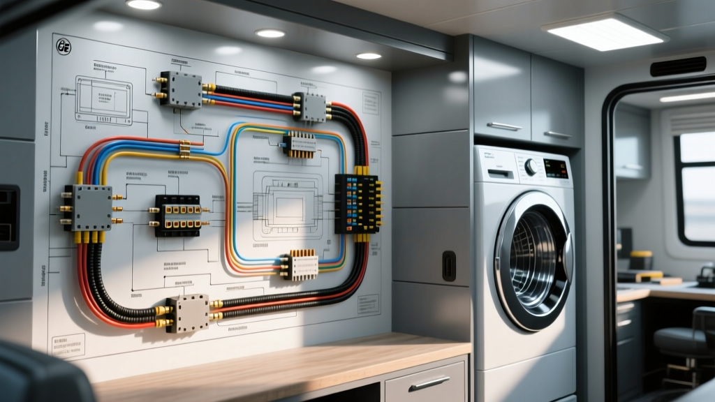
The Architecture of 240V AC in Mobile Platforms
Integrating residential appliances into automotive, RV, and marine environments requires a fundamental shift in electrical architecture. Standard mobile platforms operate on 12V DC, 24V DC, or 120V AC single-phase shore power. However, when upfitters and custom motorcoach builders search for a wiring diagram for GE electric dryer units, they are immediately confronted with the requirement for 240V AC split-phase power. A standard GE electric dryer heating element draws approximately 22 amps at 240V, while the drum motor and control circuits utilize 120V derived from one of the hot legs and the neutral.
To safely route this power in a skoolie conversion, luxury sprinter van, or expedition vehicle, you must either utilize a specialized 50A 120/240V shore power drop (NEMA 14-50) or engineer a split-phase inverter topology using stacked units (such as two Victron MultiPlus-II inverters synchronized in master/slave configuration). This reference guide details the exact schematics, wire gauges, and terminal configurations required to integrate a GE dryer into a mobile electrical system without risking catastrophic failure, voltage drop, or chassis electrification.
Step-by-Step Wiring Diagram for GE Electric Dryer (RV & Skoolie Applications)
The following schematic flow represents the power distribution from the external shore power inlet or split-phase inverter stack to the GE dryer terminal block. All routing must comply with NEC Article 551 (Recreational Vehicles) and ABYC E-11 standards for AC/DC isolation.
1. Source and Automatic Transfer Switch (ATS)
Power originates at a 50A NEMA 14-50R shore power inlet or the AC OUT terminals of a split-phase inverter stack. The L1 (120V), L2 (120V), Neutral, and Ground lines are routed through a 50A dual-pole Automatic Transfer Switch (ATS). The ATS prioritizes inverter power when shore power is disconnected, though running a 5.5kW dryer load on batteries requires a massive 48V lithium bank (minimum 400Ah) and high-current busbars.
2. Main Distribution Panel and Breaker Sizing
From the ATS, the 4-wire bundle enters the main AC distribution panel. The GE dryer requires a dedicated 30A 2-pole breaker. Do not use two independent single-pole 30A breakers; a common-trip 2-pole breaker is mandatory to ensure both L1 and L2 disconnect simultaneously during a fault condition, preventing the control board from receiving 120V while the heating element is isolated.
3. Cable Routing and Receptacle Termination
From the 30A 2-pole breaker, a 10/4 AWG SOOW (Service, Oil, Oil-resistant, Water-resistant) flexible cable is routed to a NEMA 14-30R receptacle. SOOW cable is mandatory in automotive and mobile environments because standard THHN solid-core wire will fracture under the constant vibration and chassis flex of a moving vehicle. The NEMA 14-30R must be mounted in a vibration-dampened, sealed enclosure.
Technical Specification Chart: Wire Gauge & Connector Pinouts
Proper termination is critical. Loose connections in high-draw 240V circuits generate immense heat, leading to melted receptacles and fire hazards. Use the following specifications when terminating the NEMA 14-30R and the GE dryer terminal block.
| Terminal / Pin | Wire Color Code | AWG Size | Termination Type | Torque Specification |
|---|---|---|---|---|
| X (L1 Hot) | Black | 10 AWG | Crimped Ring Terminal (10-8 AWG, #10 stud) | 14 in-lbs (1.6 Nm) |
| Y (L2 Hot) | Red | 10 AWG | Crimped Ring Terminal (10-8 AWG, #10 stud) | 14 in-lbs (1.6 Nm) |
| N (Neutral) | White | 10 AWG | Crimped Ring Terminal (10-8 AWG, #10 stud) | 14 in-lbs (1.6 Nm) |
| G (Ground) | Green / Bare | 10 AWG | Chassis Bonding Lug / Terminal Block | 20 in-lbs (2.2 Nm) |
GE Terminal Block Configuration and Bonding Strap Modification
One of the most frequent and dangerous errors made by mobile upfitters is failing to modify the GE dryer terminal block for a 4-wire mobile power system. Older residential codes allowed 3-wire setups where the neutral and ground were bonded at the appliance. In a vehicle, the chassis is already bonded to the DC negative and AC ground. Bonding the neutral to the chassis inside the dryer will cause AC return current to flow through the vehicle's metal frame, creating severe shock hazards and galvanic corrosion.
4-Wire Conversion Procedure
- Remove the terminal block access cover on the rear of the GE dryer.
- Locate the copper or aluminum bonding strap connecting the center Neutral (N) terminal to the metal chassis ground screw.
- Disconnect and remove this bonding strap entirely. Tape it inside the manual for future reference.
- Connect the White (Neutral) wire exclusively to the center silver terminal.
- Connect the Green (Ground) wire exclusively to the green chassis ground screw using a star washer to bite through the paint and ensure bare metal contact.
- Connect Black (L1) to the X terminal and Red (L2) to the Y terminal. Polarity between L1 and L2 does not matter for the heating element, but must be consistent with your split-phase inverter mapping.
Voltage Drop Calculations for Long Wheelbase Vehicles
In extended wheelbase Sprinters, Ford Transits, or full-size school bus conversions, the distance from the main distribution panel to the dryer receptacle can easily exceed 40 feet. According to NEC Article 551 and standard electrical codes, a 3% voltage drop on a 240V circuit equates to a maximum loss of 7.2V.
A standard 10 AWG copper wire has a resistance of approximately 1.018 ohms per 1,000 feet. For an 80-foot round trip (40 feet each way) carrying 25 amps (continuous load derating), the voltage drop is calculated as:
Voltage Drop = 2 × L × R × I / 1000
Voltage Drop = 2 × 40 × 1.018 × 25 / 1000 = 2.036V
While 2.036V is within the 3% limit, mobile environments suffer from high ambient temperatures inside walls and subfloors, which increases copper resistance. For runs exceeding 35 feet, upsize to 8 AWG SOOW cable to mitigate thermal voltage drop and ensure the dryer's heating element reaches optimal operating temperatures without overloading the circuit.
Troubleshooting Common Integration Faults
When testing the system post-installation, use a true-RMS digital multimeter to verify the following parameters before plugging in the GE dryer:
- L1 to L2: Must read 240V AC (±5V). If reading 0V, your split-phase inverters are out of sync or wired in parallel instead of series/split-phase.
- L1 to Neutral: Must read 120V AC.
- L2 to Neutral: Must read 120V AC.
- Neutral to Ground: Must read < 1.0V AC under load. If higher, you have a high-resistance ground connection to the vehicle chassis or a floating neutral on the inverter stack.
If the dryer drum turns but no heat is generated, verify that both poles of the 2-pole breaker are outputting 120V. A tripped half of a 2-pole breaker (rare but possible with certain RV-style breakers) will supply 120V to the motor but fail to provide the 240V potential required by the heating element. For comprehensive appliance schematics, refer to the GE Appliances Technical Support Library to trace the internal centrifugal switch and thermal fuses.
System Grounding and Chassis Bonding Requirements
Mobile platforms require a unified grounding scheme. The AC Ground (Green/Bare) from the NEMA 14-30R must be tied to the main AC ground busbar, which is permanently bonded to the vehicle's steel chassis. Furthermore, if utilizing a split-phase inverter setup, the inverters must feature an internal or external System Neutral Ground Relay. This relay ensures that when operating off-inverter (off-grid), the neutral is bonded to ground, allowing the GE dryer's internal GFCI and thermal protection circuits to function correctly. For deeper insights into mobile split-phase topologies, consult the Victron Energy Wiring Unlimited Guide.