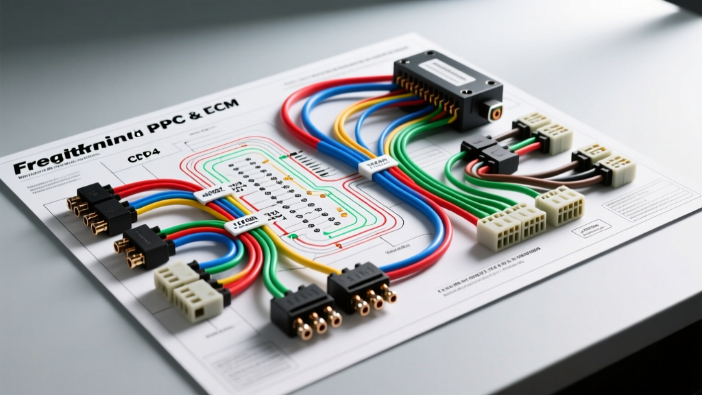
Decoding the Freightliner Multiplex Electrical Architecture
Heavy-duty commercial vehicles operate in a completely different electrical paradigm compared to light-duty passenger cars. When sourcing an accurate wiring diagram for Freightliner heavy-duty applications, particularly the Cascadia lineup equipped with Detroit Diesel DD13 or DD15 powertrains, you are not looking at simple point-to-point 12V circuits. Instead, you are dealing with a highly integrated Multiplex Electrical System governed by the Common Powertrain Controller (CPC) and the SAE J1939 Controller Area Network (CAN) bus. This advanced technical deep dive dissects the OEM wiring architecture, ECM integration, and precise pinout configurations required to diagnose, repair, and modify modern Freightliner chassis harnesses.
Unlike legacy trucks that relied on massive, heavy copper harnesses running from the dashboard to every individual component, modern Freightliner Cascadias utilize a localized multiplexing strategy. The CPC (often the CPC4 module in newer models) acts as the central gateway, translating driver inputs and chassis sensor data into J1939 CAN messages. These messages are then broadcast to the Motor Control Module (MCM) or Engine Control Module (ECM), the Aftertreatment Control Module (ACM), and the SAM (System Advisor Module) chassis nodes. Understanding this network topology is mandatory before attempting any harness repair or accessory upfit.
The J1939 CAN Bus Backbone: Physical Layer Specifications
The backbone of any Freightliner wiring diagram for the Cascadia is the J1939 CAN bus. This twisted-pair network operates at a high speed of 250 kbps and is highly susceptible to electromagnetic interference (EMI) if the physical layer specifications are compromised during repair.
- CAN High (CAN+): OEM wire color is typically Yellow (18 AWG).
- CAN Low (CAN-): OEM wire color is typically Green (18 AWG).
- Twist Rate: The wires must be twisted at a rate of at least one twist per inch (approx. 3-4 twists per 10 cm) to maintain common-mode noise rejection.
- Shielding: The twisted pair is wrapped in a braided copper shield, which must be grounded at one end only to prevent ground loops.
- Termination: The J1939 backbone requires exactly two 120-ohm terminating resistors located at the physical ends of the network (usually one inside the CPC and one inside the MCM/ECM). The total resistance measured across CAN High and CAN Low with the batteries disconnected must read 60 ohms (± 5 ohms).
If a technician improperly splices a CAN wire and untwists more than an inch of the pair, or if a terminating resistor fails open, the network impedance shifts. A reading of 120 ohms indicates a single resistor failure, which often results in intermittent SPN 625 FMI 9 (CAN bus abnormal rate of change) codes, especially when the high-amperage starter motor engages and floods the chassis with EMI.
CPC4 to ECM/MCM OEM Wiring Diagram & Pinout Reference
The CPC4 module utilizes a high-density, sealed connector system. Below is a critical reference table for the primary CPC4 120-pin connector interface, focusing on the essential power, ground, and J1939 communication circuits required to bring the powertrain online. For comprehensive circuit tracing, always cross-reference this with the official Daimler Truck North America (DTNA) Service Support portal.
| Pin Number | Circuit Function | Wire Color (OEM) | AWG Size | Diagnostic Notes |
|---|---|---|---|---|
| 1 | Battery Direct (B+) | Red | 10 AWG | Constant 12V. Maintains CPC memory. Voltage drop >0.2V indicates bulkhead corrosion. |
| 2 | Ignition Switch Power | White | 14 AWG | Switched 12V. Loss of power while driving triggers SPN 524031 FMI 3. |
| 18 | J1939 CAN High | Yellow | 18 AWG | Twisted pair with Pin 19. Idle voltage approx. 2.6V. |
| 19 | J1939 CAN Low | Green | 18 AWG | Twisted pair with Pin 18. Idle voltage approx. 2.4V. |
| 35 | Chassis Ground | Black | 10 AWG | Must be terminated to a clean, bare metal chassis stud. Max resistance to battery negative: 0.1 ohms. |
| 44 | Engine Crank Request | Purple | 16 AWG | Signal to MCM/ECM to engage starter relay. Requires clutch/neutral safety interlock validation. |
| 56 | Wake-Up Signal (SAM) | Light Blue | 18 AWG | Network management signal. Keeps modules awake during DPF regeneration cycles. |
Real-World Failure Modes: The Bulkhead Connector & Fretting Corrosion
When utilizing a wiring diagram for Freightliner chassis troubleshooting, the physical routing of the harness is just as important as the schematic. The most notorious failure point in the Cascadia lineup is the main bulkhead connector passing through the firewall. This massive multi-pin connector bridges the cab environment with the harsh, high-vibration under-hood environment.
The Fretting Corrosion Phenomenon
Micro-vibrations from the diesel engine cause the male and female copper alloy terminals inside the bulkhead connector to rub against one another. Over time, this wears away the tin or gold plating, exposing the base copper to moisture and oxygen. The resulting copper oxide acts as a semiconductor, introducing variable resistance into the circuit.
Symptom: The truck experiences random stalling, loss of throttle pedal response, or a 'Check Engine' light with multiple seemingly unrelated SPN codes (e.g., simultaneous loss of communication with the ABS module and the ACM).
Diagnostic Fix: Do not simply clear the codes. Perform a loaded voltage drop test across the bulkhead connector. Using a headlight bulb or a dedicated carbon pile load tester, draw 5-10 amps through the suspected circuit while measuring the voltage drop across the connector pins. A drop exceeding 0.1V under load confirms fretting corrosion. The repair requires depinning the connector, cleaning with specialized electrical contact cleaner, and applying a dielectric grease specifically formulated for high-fretting environments, such as Nyogel 760G.
Sensor Harness Routing and AWG Specifications
Engine sensor wiring on the Detroit Diesel DD13/DD15 platforms requires strict adherence to AWG and shielding specifications. The MCM relies on highly precise 5V reference signals; substituting 16 AWG wire for a specified 20 AWG shielded signal wire can alter the capacitance of the circuit, leading to skewed sensor readings.
| Sensor Type | Wire Gauge (AWG) | Shielding Requirement | Connector Type |
|---|---|---|---|
| Exhaust Gas Temp (EGT) | 20 AWG | High-Temp Fiberglass Braid | Deutsch DTM / Metripack |
| Boost Pressure / MAP | 18 AWG | Foil Shield (Drain wire to MCM ground) | Delphi Metripack 150 |
| Camshaft / Crankshaft Position | 18 AWG | Braided Copper Shield | Deutsch DT (3-Cavity) |
| DEF Tank Level / Temp | 16 AWG | Unshielded (Twisted Pair) | AMP Superseal 1.5 |
For authoritative connector pin insertion and extraction procedures, technicians should consult the TE Connectivity Deutsch DT Connector Specifications. Using improper extraction tools on Deutsch wedgelocks will permanently deform the secondary retention mechanism, leading to terminal back-out under heavy chassis vibration.
Best Practices for Heavy-Duty Harness Repair
When executing repairs based on any Freightliner schematic, standard automotive quick-splices and electrical tape are strictly prohibited. The under-hood environment of a Class 8 truck exposes wiring to extreme thermal cycling, diesel fuel, DEF fluid, and high-pressure steam from pressure washing.
- Solder-Seal Heat Shrink: All inline splices must use dual-wall, adhesive-lined heat shrink with a pre-installed solder ring. The hot-melt adhesive must be seen extruding from both ends of the shrink tube to guarantee a watertight seal.
- Avoid T-Taps: Never use 'scotch-lock' or T-tap connectors to tap into a J1939 CAN bus or a 5V sensor reference wire. These connectors sever strands of the base wire, reducing the effective AWG and creating a high-resistance point that will inevitably fail.
- Breakout Harnesses: If adding auxiliary equipment (e.g., PTO controls, auxiliary lighting, or snowplow prep), always use OEM-approved breakout harnesses that plug inline between existing sealed connectors. Never pierce the insulation of the main chassis harness.
Advanced Diagnostics: Utilizing Suspect Parameter Numbers (SPN)
Modern Freightliner diagnostics rely on the SAE J1939 standard for fault codes, utilizing SPN (Suspect Parameter Number) and FMI (Failure Mode Identifier) combinations. A deep understanding of the wiring diagram allows a technician to map an SPN directly to a physical pin on the CPC or MCM.
For example, if the diagnostic tool pulls SPN 91 (Accelerator Pedal Position) FMI 3 (Voltage Above Normal)
For comprehensive J1939 protocol standards and FMI definitions, refer to the SAE International J1939 Standards documentation. Mastering the wiring diagram for Freightliner Cascadia models requires a shift from traditional 12V DC circuit theory to a network-level understanding of multiplexed communication, precise physical layer tolerances, and heavy-duty environmental sealing. By respecting the J1939 architecture, utilizing proper heavy-duty repair materials, and leveraging loaded voltage-drop testing, technicians can ensure maximum uptime and reliability for these critical commercial assets.Conclusion